MB54XX-X Modbus Gateway User’s Manual v. 1.
Atop Modbus Gateway MB54XX-X Series User’s Manual V 1.1 Important Announcement The information contained in this document is the property of Atop technologies, Inc., and is supplied for the sole purpose of operation and maintenance of Atop Technologies, Inc., products.
Atop Modbus Gateway MB54XX-X Series User’s Manual V 1.1 Table of Contents Preface ....................................................................................................................................................... 2 1 2 3 Introduction ................................................................................................................................... 4 1.1 Overview .........................................................................................................
Atop Modbus Gateway MB54XX-X Series User’s Manual V 1.1 3.8 3.8.1 3.8.2 3.8.3 3.8.4 3.8.5 3.8.6 Log Settings .................................................................................................... 38 System Log ..................................................................................................... 39 Data Log ........................................................................................................... 40 Modbus Statistic ...........................................
Atop Modbus Gateway MB54XX-X Series User’s Manual V 1.1 Preface Purpose of the Manual This manual supports you during the installation and configuring of the MB54XX Modbus Gateway Series only, as well as it explains some technical options available with the mentioned product.
Atop Modbus Gateway MB54XX-X Series User’s Manual V 1.1 interference to radio communications. Operation of this equipment in a residential area is likely to cause harmful interference in which case the user will be required to correct the interference at his own expense. This device complies with Part 15 of the FCC Rules.
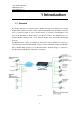
Atop Modbus Gateway MB54XX-X Series User’s Manual V 1.1 1 Introduction 1.1 Overview The Modbus Gateway is an interface between Modbus Gateway and computer hosts running Modbus/TCP on Ethernet networks. Fully compliant with Modbus/TCP, the Modbus Gateway offers a convenient solution to connect existing devices or controllers running Modbus serial protocol (Modbus/ASCII or Modbus/RTU) to an Ethernet network.
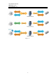
Atop Modbus Gateway MB54XX-X Series User’s Manual V 1.1 Fig. 1.
Atop Modbus Gateway MB54XX-X Series User’s Manual V 1.1 1.
Atop Modbus Gateway MB54XX-X Series User’s Manual V 1.1 2 Getting Started 2.1 Inside the Package Inside the purchased you will find the following items. Table 2.
Atop Modbus Gateway MB54XX-X Series User’s Manual V 1.1 How to order Please refer to the following product codes to place an order. Table 2.
Atop Modbus Gateway MB54XX-X Series User’s Manual V 1.1 2.2 Appearance, Front & Rear Panels The following figures show the device’s front and rear panels. MB5404D-X (Left) / MB5404D-Sis-X (Right) Front Panel Fig. 2.
Atop Modbus Gateway MB54XX-X Series User’s Manual V 1.1 MB5416-X Front and Rear Panel Fig. 2.
Atop Modbus Gateway MB54XX-X Series User’s Manual V 1.1 MB5408-X Front and Rear Panel Fig. 2.
Atop Modbus Gateway MB54XX-X Series User’s Manual V 1.1 2.3 First Time Installation Before installing the device, please adhere to all safety procedures described below, Atop will not be held liable for any damages to property or personal injuries resulting from the installation or overall use of the device. Do not attempt to manipulate the product in any way if unsure of the steps described here, in such cases please contact your dealer immediately. 1.
Atop Modbus Gateway MB54XX-X Series User’s Manual V 1.1 2.4 Factory Default Settings Network Defaults Note that the Modbus Gateway comes with one IP address for redundant Ethernet interfaces. Table 2. 3 Interface Device IP Subnet mask Gateway IP LAN 1 10.0.50.100 255.255.0.0 10.0.0.254 Modbus Default Table 2.
Atop Modbus Gateway MB54XX-X Series User’s Manual V 1.1 Other Default Settings are shown in the following table: Table 2. 5 Parameter Default Values Security User Name Admin Password Null (blank) SNMP SysName of SNMP 0060E9-XXXXXX SysLocation of SNMP Location SysContact of SNMP Contact SNMP Enable Read Community Public Write Community Private SNMP Trap Server 0.0.0.0 Note: you can press the “Reset” button on the front panel for 5 seconds (see Sec. 3.8.8 and 3.
Atop Modbus Gateway MB54XX-X Series User’s Manual V 1.1 3 Configuration and Setup 3.1 Locating and IP configuring using Device View© First, please install our configuration utility program Device View© that comes with the Product CD or download it from our websites (www.atop.com.tw or www.atop-tech.com). For more information on how to install Device View© , please refer to the manual that comes in the utility CD.
Atop Modbus Gateway MB54XX-X Series User’s Manual V 1.1 Fig. 3. 2 Fig. 3. 3 You may proceed then to change the IP address, to avoid any IP address conflict with other hosts on your LAN network or to connect the device to your existing LAN. The system will prompt you to Authorize whether you can do these changes or not, i.e., it will ask you for the Username and Password, (Fig. 3.4).
Atop Modbus Gateway MB54XX-X Series User’s Manual V 1.1 Fig. 3. 4 Please consult your system administrator if you do not know your network subnet mask and gateway address. If your LAN network address begins with 192.168.X.X, then please use the LAN2 interface for configuration. 3.2 Configuration using Web Interface Every MB54XX Modbus Gateway device is equipped with a built-in Web server in the firmware.
Atop Modbus Gateway MB54XX-X Series User’s Manual V 1.1 Fig. 3. 6 This type of configuration is the most user-friendly, most recommended and most common method used on your MB54XX Modbus Gateway. Please go to its corresponding section for a detailed explanation.
Atop Modbus Gateway MB54XX-X Series User’s Manual V 1.1 3.2.1 LCM (Liquid Crystal Matrix) Configuring (MB5408-X/5416-X only) The device also has the option of manual configuration (without the software), by making use of its interactive console. Using this method is however, very easy and intuitive; buttons and their functions are described next. Table 3.
Atop Modbus Gateway MB54XX-X Series User’s Manual V 1.1 To enter: 3. Net mask Use / to increase or decrease the Digital of subnet mask and then
Atop Modbus Gateway MB54XX-X Series User’s Manual V 1.1 1. 300 Display or Change baud rate 2. 600 3. 1200 4. 2400 5. 4800 6. 9600 1.Baud Rate 7. 19200 8. 38400 9. 57600 10. 115200 11. 230400 12. 460800 13. 921600 1. None Display or Change Parity mode 2.Parameter set 2. Odd 2.Parity 3. Even 4. Mark 5.Space 1. 5 bits 3.Data bits Display or Change Data bit length 2. 6 bits 3. 7 bits 4. 8 bits 1. 1 bits Display or Change Stop bit length 4.Stop bits 2. 2 bits 1. None 5.Flow control 2. Xon/Xoff 3.
Atop Modbus Gateway MB54XX-X Series User’s Manual V 1.1 1. 232 6.UART mode 2. 422 3. 485 Display or Change UART mode for RS-232 Display or Change UART for RS-422 Display or Change UART for RS-485 1.No 7.Apply to all 2.Yes Apply UART setting to all serial ports 1.Disable Disable Web console 2.Enable Enable Web console 1.Disable Disable Telnet console 2.Enable Enable Telnet console 1.Web console 1.Console 2.Telnet console 1.No 1.LCM console 2.Yes 4.Server state 2.Pwd protection 1.
Atop Modbus Gateway MB54XX-X Series User’s Manual V 1.1 3.2.2 Configure Automatic IP Assignment with DHCP A DHCP server can automatically assign addresses to LAN1 or LAN2, the Subnet Mask, and the Gateway. You can simply check “DHCP” box in the Network Setting dialog using our Device View© utility and then restart it; once restarted it will be automatically configured. 3.3 Web Overview In this section, only current information on the device’s status and settings will be displayed. Fig. 3.
Atop Modbus Gateway MB54XX-X Series User’s Manual V 1.1 3.4 Network Configuration In this section, IP, Subnet Mask and overall connectivity settings can be accessed. When on 1 Redundancy Mode the device will have the two LAN ports connected to the Network, but the signal will flow through one of them. In the case one line is out due to any reason there will still be another route so the signal can keep flowing. Fig. 3.
Atop Modbus Gateway MB54XX-X Series User’s Manual V 1.1 When the device is set on Dual Subnet Mode, a set of two IP addresses can be used without having Redundancy. This is especially useful when using two different networks. Fig. 3.
Atop Modbus Gateway MB54XX-X Series User’s Manual V 1.1 3.5 Basic Settings 3.5.1 COM Settings This section is responsible for settings on your physical ports, (may them be COM or serial). Fig. 3.
Atop Modbus Gateway MB54XX-X Series User’s Manual V 1.1 3.5.2 Operation Mode RTU Slave: when working as a slave node, the device will wait and accept request from its master; data transfer is done under an RTU format. RTU Master: when working as a master node, the device will issue commands to the slave node; data transfer is under an RTU format. ASCII Slave: when working as a slave node, the device will wait and accept request from its own master; data transfer is under an ASCII format.
Atop Modbus Gateway MB54XX-X Series User’s Manual V 1.1 3.5.4 VCOM Settings Generates a virtual Serial (COM) port within the device by the network connection, it is a TCP connection but the encoding is an Atop Technologies’ exclusive private protocol. There is the choice to set your device as either a Master or a Slave in your network. You will need a VCOM setting, proceed to go to Basic Settings → VCOM Settings and tick on the VCOM’s “Enable” box to allow configuration on the port selected.
Atop Modbus Gateway MB54XX-X Series User’s Manual V 1.1 Fig. 3. 12 VCOM inactivity’s Time Out can be set as well (which is the period of time allowed between actions), with a maximum of 600 minutes or 10 hours. If no action has been taken after this period, VCOM connection will be automatically interrupted by the system. It is important to note that alternatively, these settings can be chosen to be applied to All VCOMs if needed by checking the last box on the options. Fig. 3.
Atop Modbus Gateway MB54XX-X Series User’s Manual V 1.1 3.5.5 TCP Settings Settings for representing a Modbus TCP connection using the internet are set here. First go to Basic Settings ↔ TCP Settings, then proceed to choose whether to enable TCP ticking on the “Enable” box. Fig. 3. 14 TCP Slave: When on this mode, the device will run on Slave mode and wait to receive Modbus requests from the Master; data transmission is done under a Modbus TCP format.
Atop Modbus Gateway MB54XX-X Series User’s Manual V 1.1 Fig. 3. 15 On Operation Mode choose whether the device is going to be a Slave or a Master. Remote IP Address refers to the IP belonging to the device that is going to be controlled from your MB54XX Series; this option is not available when the device is set as a Master. TCP Port is the port through which the signal is going to be relayed upon.
Atop Modbus Gateway MB54XX-X Series User’s Manual V 1.1 3.5.6 Slave ID Map The system uses the Modbus ID to route Modbus’ request commands (from the master node) to the respective slave node; it is paramount to define ID maps for each slave node. For every slave node, there must be a correct Virtual ID (Alias ID) and Real ID defined in the maps. Fig. 3.
Atop Modbus Gateway MB54XX-X Series User’s Manual V 1.1 Slave Interface When a port is set to slave mode, a Slave interface will be then created for you. Select the Slave Interface, which is the COM/VCOM/TCP port; then select Alias Mode or Offset Mode to modify the range and offset as you needed. Alias Mode maps a virtual ID to a real ID each at the time. Alias ID which refers to a Virtual ID for the reading Master node. Real ID which is the real ID from the slave node.
Atop Modbus Gateway MB54XX-X Series User’s Manual V 1.1 3.6 Advanced Settings 3.6.1 SNMP Settings SNMP Settings determines whether your device settings can be viewed with standard SNMP software; by default it is disabled. SysName which is by default the MAC address SysLocation refers to the device’s physical location. SysContact is the device administrator’s contact information.
Atop Modbus Gateway MB54XX-X Series User’s Manual V 1.1 3.6.2 Modbus In Modbus settings, you could select whether to enable Modbus Exception or not. If the Modbus’ slave produces no response, timeout occurs, it may then be necessary for the gateway to return an Exception, and setting the Response timeout as follows. Configure timeout for each COM port Configure timeout for TCP/ VCOM port Fig. 3.
Atop Modbus Gateway MB54XX-X Series User’s Manual V 1.1 3.7 Alert Configuration 3.7.1 SMTP and Email Settings In Alert Events, you can configure options to let your Modbus Gateway to send out device information to alert users, administrators, or responsible personnel. There are five anomalies defined in it to trigger alert functions. Cold Start, power supply is interrupted. Warm Start, the device Restart function is used, (either by pressing a button or by its interface).
Atop Modbus Gateway MB54XX-X Series User’s Manual V 1.1 When enabled, an E-mail alert would be sent to the designated E-mail address in the E-Mail Settings. To setup an email alert function, you first need to configure the recipient’s email address and the mail server. Fig. 3.
Atop Modbus Gateway MB54XX-X Series User’s Manual V 1.1 3.8 System 3.8.1 Log Settings This section lets you change the way your report will be shown on your Log. Fig. 3.
Atop Modbus Gateway MB54XX-X Series User’s Manual V 1.1 3.8.2 System Log This section merely shows a list of system running events currently (with every event’s properties displayed), as well as the option to clear them all. Fig. 3.
Atop Modbus Gateway MB54XX-X Series User’s Manual V 1.1 3.8.3 Data Log Event filtering is available in this section for analysis; a number of options are available for a customized analysis. Traffic in the system can be done here as well. Fig. 3.
Atop Modbus Gateway MB54XX-X Series User’s Manual V 1.1 3.8.4 Modbus Statistic All ports’ information is available in this section. Fig. 3.
Atop Modbus Gateway MB54XX-X Series User’s Manual V 1.1 3.8.5 Time Date and time can be set manually, or using Network Time Protocol (NTP) to automatically synchronizes with a Time Server. For auto-synching check the box below NTP Server Settings “Obtain date/time automatically” proceeding then to fill the IP address or hostname for it. If a hostname is entered, the DNS server must be configured properly; a Time Zone can be selected as well, Fig. 3.26. Fig. 3.
Atop Modbus Gateway MB54XX-X Series User’s Manual V 1.1 3.8.6 Security Password settings are available at this section, as well as device’s console configuration settings allowing users to limit the way they are able to configure the device. Fig. 3.
Atop Modbus Gateway MB54XX-X Series User’s Manual V 1.1 3.8.7 Import/Export Once all the configurations are set and the device is working properly, you may want to backup (Export) your configuration. Backup can be used when the new firmware is uploaded and it is reset to a factory default settings, it is done to prevent accidental loading of incompatible old settings.
Atop Modbus Gateway MB54XX-X Series User’s Manual V 1.1 Fig. 3. 29 Fig. 3.
Atop Modbus Gateway MB54XX-X Series User’s Manual V 1.1 3.8.8 Factory Default A simple return to Factory Default is available in our MB54XX Series. Fig. 3.
Atop Modbus Gateway MB54XX-X Series User’s Manual V 1.1 3.9 Restart Restart is just a click away in our Modbus Series. Fig. 3.
Atop Modbus Gateway MB54XX-X Series User’s Manual V 1.1 4 Applications and Examples On your device two different ID mapping definitions are given by the system, both using Modbus ID to route the requesting command (from the Master) to the Slave node. 4.1 Using ID offset range mapping If the Slave ID is continuous, it is recommended to use the Offset mode, Fig. 4.1. Fig. 4.
Atop Modbus Gateway MB54XX-X Series User’s Manual V 1.1 Fig. 4.
Atop Modbus Gateway MB54XX-X Series User’s Manual V 1.1 4.2 Using Alias ID mapping This is only recommended if the ID is not continuous, Fig. 4.3. Fig. 4.
Atop Modbus Gateway MB54XX-X Series User’s Manual V 1.1 Fig. 4.
Atop Modbus Gateway MB54XX-X Series User’s Manual V 1.1 5 Specifications 5.1 Hardware Table 5. 1 System CPU 32-bit 266MHz RISC Processor with MMU Flash Memory 2 + 8 MB (2MB for Bootloader) RAM 128 MB DDR EEPROM 8 KB Reset Built-in Recessed Key (Restore to Factory Defaults) Watchdog Hardware built-in Network Ethernet Interface Protection IEEE 802.3 Compliance Dual Port 10/100Mbps Auto-Detection Connection: RJ-45 Auto MDI/MDI-X: No Built-in 1.
Atop Modbus Gateway MB54XX-X Series User’s Manual V 1.
Atop Modbus Gateway MB54XX-X Series User’s Manual V 1.1 Input Consumption EMC 100~240 V (MB5408-X, MB5416-X) DC9~48V (MB5404D-X, MB5404D-Sis-X) Max. 8.5 W (MB5408-X/MB5416-X) 5.58W (MB5404D-X, MB5404D-Sis-X) FCC Class A, CE Class A Mechanical MB5408-X, MB5416-X 436 x 43.5 x 200 MB5404D-X, MB5404D-Sis-X 53.4x145.7x119.
Atop Modbus Gateway MB54XX-X Series User’s Manual V 1.1 Serial and RJ-45 Connectors Pin Assignments RJ45 to Serial Connectors Table 5.
Atop Modbus Gateway MB54XX-X Series User’s Manual V 1.1 DB9 to RS-232/RS-485/RS-422 connectors (MB5404D-X) Table 5.
Atop Modbus Gateway MB54XX-X Series User’s Manual V 1.1 5pin Terminal Block to RS-485/RS-422 connectors (MB5404D-Sis-X) Table 5.
Atop Modbus Gateway MB54XX-X Series User’s Manual V 1.1 RJ45 to Male DB9 Connector Table 5. 5 RJ45 Male DB9 RTS Pin 1 Pin 7 RTS DTR Pin 2 Pin 4 DTR TXD Pin 3 Pin 3 TXD SG Pin 4 Pin 5 GND SG Pin 5 RXD Pin 6 Pin 2 RXD DSR Pin 7 Pin 6 DSR CTS Pin 8 Pin 8 CTS RS-232/RS-422 to RJ-45 Cross over Connection Table 5.
Atop Modbus Gateway MB54XX-X Series User’s Manual V 1.1 RS-485 to RJ-43 Loop back Connection Table 5. 7 RJ45 A RJ45 B RS-485 RS-485 Pin 1 Pin 1 Pin 2 Pin 2 Pin 3 Pin 3 Pin 4 Pin 4 Pin 5 Pin 5 Data+ Pin 6 Pin 6 Data+ Data- Pin 7 Pin 7 Data- Pin 8 Pin 8 LED indicators Table 5.
Atop Modbus Gateway MB54XX-X Series User’s Manual V 1.1 (Blinking Green) Ethernet Port in Activity 5.2 Software Table 5.
Atop Modbus Gateway MB54XX-X Series User’s Manual V 1.1 Appendix Configuration using Telnet Interface The MB54XX Modbus Gateway device also has a built-in Telnet server program such that users can also configure the device using Telnet console software. To start the device configuration using Telnet console, please go to Windows Command software (Start→Run) and use “telnet” command to access the device. In the “Run” window, enter “telnet device_IP_address” (For example, telnet 10.0.50.
Atop Modbus Gateway MB54XX-X Series User’s Manual V 1.1 For Telnet interface configuring, please go to Windows® Hyper Terminal and follow the steps described below. On your Desktop go to “Start → All Programs → Accessories → Communications → HyperTerminal”. Apx.
Atop Modbus Gateway MB54XX-X Series User’s Manual V 1.1 Fill the Name entry with a name of your choice, and select your favorite icon. The “Connect to” window will pop-out. Apx. 2 Select “TCP/IP Winsock” on “Connect using”, then check “OK”. Here “Session 1-Hyperterminal” will appear, and then type “telnet 10.0.XXX.XXX” (device’s IP), to get into the device’s login menu. Apx.
Atop Modbus Gateway MB54XX-X Series User’s Manual V 1.1 Once the correct username and password are entered, you will see the configuration menu of the device on the display. Apx.
Atop Modbus Gateway MB54XX-X Series User’s Manual V 1.1 The steps before mentioned are for Win XP, in order to enable telnet in Win 7 follow the steps below. 1. Go to Start and on the “Run” box type cmd, Fig. Apx.
Atop Modbus Gateway MB54XX-X Series User’s Manual V 1.1 2. A pop out window will appear as follows, type “ pkmgr /iu:”TelnetClient” ” and press Enter, your Telnet must be configured by now. If you wish to confirm if it is working, follow the next step. Apx. 3. 6 Go to Control Panel under Programs and Features press Turn Windows features on or off and click the Telnet Client box. Apx.
Atop Modbus Gateway MB54XX-X Series User’s Manual V 1.1 After these steps are completed, telnet can be accessed by typing the device’s IP using the “Run” command window on the Start programs. Apx. 8 Apx.
Atop Modbus Gateway MB54XX-X Series User’s Manual V 1.1 Its main menu is a command driven interface; it will look as follows. Apx. 10 Most options appear the same as the ones in web browsing mode, the difference being that they have to be accessed by entering the number corresponded to that option. For accessing each function please follow the steps described below.
Atop Modbus Gateway MB54XX-X Series User’s Manual V 1.1 On the Main Screen → [1] Overview, (a more detailed description of this section is given on Sec. 3.3) Apx.
Atop Modbus Gateway MB54XX-X Series User’s Manual V 1.1 Main Screen → [2] Networking, (a more detailed description of this section is given on Sec. 3.4) Apx.
Atop Modbus Gateway MB54XX-X Series User’s Manual V 1.1 Main Screen → [2] Networking → [1]LAN 1 Settings, (a more detailed description of this section is given on Sec. 3.4) Apx.
Atop Modbus Gateway MB54XX-X Series User’s Manual V 1.1 Main Screen → [2] Networking → [2] DNS Settings, (a more detailed description of this section is given on Sec. 3.4) Apx.
Atop Modbus Gateway MB54XX-X Series User’s Manual V 1.1 Main Screen → [2] Networking → [3] SNMP Settings, (a more detailed description of this section is given on Sec. 3.6.1) Apx.
Atop Modbus Gateway MB54XX-X Series User’s Manual V 1.1 COM Port Configuration: telnet Main Screen → [3] COM Port Setting, (a more detailed description of this section is given on Sec. 3.5.1) Apx.
Atop Modbus Gateway MB54XX-X Series User’s Manual V 1.1 Main Screen → [3] COM Port Setting → [1-16] Select Port → [3] COM Port Settings, (a more detailed description of this section is given on Sec. 3.5.1) Apx.
Atop Modbus Gateway MB54XX-X Series User’s Manual V 1.1 Main Screen → [4] Security, (a more detailed description of this section is given on Sec. 3.8.6) Apx.
Atop Modbus Gateway MB54XX-X Series User’s Manual V 1.1 Main Screen → [4] Security → [1] Change Password, (a more detailed description of this section is given on Sec. 3.8.6) Apx.
Atop Modbus Gateway MB54XX-X Series User’s Manual V 1.1 Reset to Factory Defaults Main Screen → [5] Set to Default, (a more detailed description of this section is given on Sec. 3.8.8) Apx.
Atop Modbus Gateway MB54XX-X Series User’s Manual V 1.1 Restart Main Screen → [6] Restart, (a more detailed description of this section is given on Sec.3.9) Apx.
Atop Modbus Gateway MB54XX-X Series User’s Manual V 1.1 Warranty Limited Warranty Conditions Products supplied by Atop Technologies Inc., are covered in this warranty for undesired performance or defects resulting from shipping, or any other event deemed to be the result of Atop Technologies Inc., mishandling.
Atop Modbus Gateway MB54XX-X Series User’s Manual V 1.1 Warranty Atop Technologies Inc., gives a 5 years max for Modbus Gateway products.