SE5001 Serial Device Server User’s Manual Version 1.6 September 2011 Tel: 886-3-5508137 Fax: 886-3-5508131 http://www.atop.com.
User Manual Version 1.6 SE5001 Serial Device Server Important Announcement The information contained in this document is the property of Atop Technologies, Inc. and is supplied for the sole purpose of the operation and maintenance of products of Atop Technologies, Inc.
User Manual Version 1.6 SE5001 Serial Device Server This document is intended to provide customers with brief descriptions on the product and to assist customers to get started. For detail information and operations of the product, please refer to the manual in the CD attached. FCC WARNING Class A for Serial Device Server (Model SE5001) This equipment has been tested and found to comply with the limits for a Class A digital device pursuant to Part 15 of the FCC rules.
User Manual Version 1.6 SE5001 Serial Device Server Contents 1. Introduction ................................................................................................... 6 1.1 SE5001 Series Comparison .......................................................................................... 6 1.2 Packaging ..................................................................................................................... 6 1.3 Application Connectivity ...............................................
User Manual Version 1.6 SE5001 Serial Device Server 3.3.7. LINK Mode: Configure SE5001 as a TCP Client ........................................ 33 3.3.8. Link Mode: Configure SE5001 in UDP ....................................................... 35 3.3.9. TCP Server Application: Enable Virtual COM ............................................. 35 3.3.10. TCP Server Application: Enable RFC 2217 ................................................ 36 3.3.11. TCP Client Application: Enable Virtual COM ....
User Manual Version 1.6 SE5001 Serial Device Server 6.3 Use TCPTEST.exe or TCPTEST2.exe Sample Program ............................................. 69 Appendix A: Specifications .........................................................................70 A.1 Hardware Specifications ............................................................................................. 70 A.2 Software Specifications ............................................................................................... 71 A.
User Manual Version 1.6 SE5001 Serial Device Server 1. Introduction SE5001, the Ethernet Serial device server is a gateway between Ethernet (TCP/UDP) and RS-232/RS-422/RS-485 communications. The information transmitted by SE5001 is transparent to both host computers (Ethernet) and serial devices (RS-232/RS-422/RS-485).
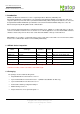
User Manual Version 1.6 SE5001 Serial Device Server Optional Accessories Name Part Number Description DK-25 30200000000022G DIN-Rail Kit UN305-0510(US-DC) 50500051500001G DC jack (1.35/3.5/7.5 mm) power adaptor, 100-240VAC input, 1.0A @ 5 VDC output, US plug UNE305-0510(EU-DC) 50500051500011G DC jack (1.35/3.5/7.5 mm) power adaptor, 100-240VAC input, 1.0A @ 5 VDC output, EU plug US315-12(US-TB3) 70100000000027G 3-pin Terminal block (5.08 mm) power adaptor, 100-240VAC input, 1.
User Manual Version 1.6 SE5001 Serial Device Server Figure 1.2 TCP Client Mode UDP Mode:UDP is a faster but connectionless network protocol. It does not guarantee the delivery of network datagrams. SE5001 can be configured to transfer data using unicast or multicast UDP from the serial device to one or multiple host computers. Data can be transmitted between serial device and host computer in both directions. Figure 1.
User Manual Version 1.6 SE5001 Serial Device Server The serial device would be unaware of the change in the communication medium. Figure 1.1 Tunneling Mode Copyright © 2011 Atop Technologies, Inc. All rights reserved. Designed in Taiwan.
User Manual Version 1.6 SE5001 Serial Device Server 2. Hardware Installation NOTE: 1. Find SE5001 Panel layout in section A.3.1 Panel Layout. 2. SE5001-S5-TB5 has a TB5 serial interface instead of DB9. 3. Press the reset button on SE5001 to reset the settings back to the default value Figure 2.1 SE5001 Interfaces (SE5001, SE5001-S2, SE5001-S5, SE5001-S5-TB5) Copyright © 2011 Atop Technologies, Inc. All rights reserved. Designed in Taiwan.
User Manual Version 1.6 SE5001 Serial Device Server Figure 2.2 SE5001 Interfaces (SE5001-S5is) 2.1 Installation Procedure Step 1: Connect SE5001 to a power source using its 5V DC Jack or its 9-30V DC Terminal Block. Note that the DC Jack is 5V only and should be used with a power adaptor. Note:SE5001 provides two power inputs that can be connected simultaneously to different DC power sources.
User Manual Version 1.6 SE5001 Serial Device Server Attention This product is intended to be grounded properly. Please do so via the Frame Ground. Copyright © 2011 Atop Technologies, Inc. All rights reserved. Designed in Taiwan.
User Manual Version 1.6 SE5001 Serial Device Server 3. Software Setup SE5001 Ethernet Serial device server is shipped with default settings shown in the following table: Property Default Value IP Address 10.0.50.100 Gateway 10.0.0.254 Subnet Mask 255.255.0.0 User Name admin Password Null(leave it blank) COM 1 9600,None, 8, 1, No flow control, buffer disabled, packet delimiter timer 2ms Link 1 Type: TCP Server, Listen port 4660, Filter=0.0.0.
User Manual Version 1.6 SE5001 Serial Device Server Figure 3.1 Configure by SerialManager Figure 3.2 Static IP setup dialog window 3.1.2. Auto IP (Dynamic IP) A DHCP server can automatically assign an IP address and network settings to SE5001. By default, the DHCP function in SE5001 is disabled. Use SerialManager to enable the DHCP function. ->Execute SerialManager (Figure 3.1) ->In SerialManager, click on the SE5001 that needs to be configured. Copyright © 2011 Atop Technologies, Inc.
User Manual Version 1.6 SE5001 Serial Device Server ->Click on “Configuration”->”Network” or the “Network” button. ->Enable “DHCP” on the Network Settings window (Figure 3.3). ->Click “OK” and SE5001 will restart and get an IP from the DHCP server automatically. Figure 3.3 SerialManager Auto IP Dialog Window 3.2 Configuration by Telnet Utility One can use Telnet utility to change configuration settings of SE5001 by following steps: 3.2.1.
User Manual Version 1.6 SE5001 Serial Device Server Figure 3.5 Main menu Note: 1. If SE5001 does not receive any commands within 1 minute, Telnet connection will terminate automatically. 2. After “0. Exit” is selected, the console will ask the user to save the configurations. 3. Changes to networking parameters will take effect only SE5001 is restarted. ->Select “1” from “Input choice and enter (0~4):” to enter “Overview” (Figure 3.6): Figure 3.
User Manual Version 1.6 SE5001 Serial Device Server 3.2.2. Networking Select “2” from “Input choice and enter (0~4):” to enter Networking page as following (Figure 3.7): Figure 3.7 Network settings Change network settings of the device including IP address, subnet mask, gateway IP address and SNMP information on this page. Please note that any changes made on this page won’t take effect until the device is restarted. Note: Press “ESC” key to return to the previous menu.
User Manual Version 1.6 SE5001 Serial Device Server 3.2.3. Change the Password 1. Select “3” from “Input choice and enter (0~4):” the following screen appears. (Figure 3.8) Figure 3.8 Change the Password 3.2.4. COM1 Setup Select “4” from “Input choice and enter (0~4):” the following screen appears (Figure 3.9): Figure 3.
User Manual Version 1.6 SE5001 Serial Device Server 3.2.5. Configure SE5001 as TCP server Figure 3.10 Link Mode: TCP Server Setup Type 1 (Link Mode) from “Input choice and enter (1~4):” of COM1 Type 1 (TCP Server) in the “Input choice(1~5) and enter:” Input local port in the “Please input local port:” To Enable IP filter: Input y in the “Do one want to enable IP filter(y/n)?” to enable IP Filter. Otherwise input n.
User Manual Version 1.6 SE5001 Serial Device Server 3. If IP filter is enabled, only source IP assigned can connect to SE5001’s COM. 4. If the multi-connection firmware is installed, SE5001 will prompt for “Multi_Port”, meaning multiple connection 3.2.6. Configure SE5001 as TCP Client Figure 3.
User Manual Version 1.6 SE5001 Serial Device Server 3.2.7. Configure SE5001 as UDP UDP is a connectionless protocol. It is faster than TCP, but does not guarantee packet delivery to the remote host. Figure 3.12 shows how to setup UDP. Figure 3.
User Manual Version 1.6 SE5001 Serial Device Server Figure 3.13 Configure Virtual COM 3.2.9. Enable / Disable Pair Connection Enable or disable “Pair Connection” on this page. For more information on how to configure two serial device servers to work in pair connection, please refer to the pair connection section 3.3.13. Copyright © 2011 Atop Technologies, Inc. All rights reserved. Designed in Taiwan.
User Manual Version 1.6 SE5001 Serial Device Server Figure 3.14 Configure Pair Connection 3.2.10. COM Port Setting Type 2 from “Input choice and enter (1~4):” of COM1, the following screen appears. It is possible to give the COM port alias name, set the baud rate and parity, determine number of data bit and stop bit, and the type of flow control to use here (Figure 3.15). Copyright © 2011 Atop Technologies, Inc. All rights reserved. Designed in Taiwan.
User Manual Version 1.6 SE5001 Serial Device Server Figure 3.15 COM Port Settings 3.2.11. Emptying Serial Buffer when TCP connection is established Figure 3.16 Com Port: Enabling Serial Buffer Type 3 from “Input choice and enter (1~4):” of COM1, by default COM port serial buffer is enabled meaning that once a TCP connection is established, old serial data received from serial device before the connection will be Copyright © 2011 Atop Technologies, Inc. All rights reserved. Designed in Taiwan.
User Manual Version 1.6 SE5001 Serial Device Server emptied. If this option is disabled, SE5001 will keep old serial data when the connection is broken (Figure 3.16). 3.2.12. Setting Packet Delimiter Packet delimiter is a way of packaging serial data. It can prevent serial data from being truncated by packing them in the same Ethernet packet. SE5001 provides two kinds of packet delimiter: Timer and Character. The default timer is 2 ms (0ms to disable this function).
User Manual Version 1.6 SE5001 Serial Device Server Figure 3.18 Setting Packet Delimiter: Character Pattern 3.2.13. Accept Control Command from COM port SE5001 can also accept serial control commands (RFC2217) directly from the COM port. For more detail about this function, please contact our Technical Support for more information. 3.2.14. Backup EEPROM to Flash Select “5” from “Input choice and enter (0~5):” the following screen should appear (Figure 3.19): Figure 3.
User Manual Version 1.6 SE5001 Serial Device Server 3.3 Configuration Using Web Browser 1. Make sure the PC is located in the same network sub-net as SE5001 2. Open a web browser, then Enter in the IP address of SE5001. Default user name is admin and default password is null (leave it blank). 3. SE5001’s network, link mode and COM ports settings can be configured in different web pages. 4. Click “Save Configuration” to save settings. 5.
User Manual Version 1.6 SE5001 Serial Device Server Figure 3.21 Overview Copyright © 2011 Atop Technologies, Inc. All rights reserved. Designed in Taiwan.
User Manual Version 1.6 SE5001 Serial Device Server 3.3.2. Networking Setup Configure IP, SNMP, and alert settings on this page. Please fill in the IP information in the fields under the TCP/IP header (Figure 3.22). Alternatively, enable DHCP to obtain IP address, gateway and subnet mask from a DHCP server automatically. Figure 3.22 IP Information Setup Enable SNMP and Alert Events by checking “Enable” (Figure 3.23). Fill in SNMP information in the fields under the SNMP header.
User Manual Version 1.6 SE5001 Serial Device Server Figure 3.23 SNMP Setup After all the settings are entered, please click on the “Save Configuration” button to save the changes. Note that the settings would become active only after SE5001 is restarted. 3.3.3. Security Setup Change the login password on this page (Figure 3.24). Copyright © 2011 Atop Technologies, Inc. All rights reserved. Designed in Taiwan.
User Manual Version 1.6 SE5001 Serial Device Server Figure 3.24 Security Setup Please enter the old password in the “Old Password” field and enter the new password in the “New Password” and the “Verified Password” fields. Then click on the “Save Configuration” to save and apply the new password. Note: Press the reset button next to the RJ-45 Jack to reset the settings back to the default value. 3.3.4.
User Manual Version 1.6 SE5001 Serial Device Server SE5001 supports different Link Modes, which are TCP Server, TCP Client, and UDP (Figure 3.25). Under the three Link Modes, TCP Server can support Virtual COM, Pair Connection, or Reverse Telnet applications. TCP Client can support Virtual COM or Pair Connection application. If none of the application is enabled, the SE5001 will run in RAW mode. In the upcoming sections, we will discuss how to setup different Link Modes properly. Figure 3.
User Manual Version 1.6 SE5001 Serial Device Server Figure 3.26 TCP Server Setup Note: LINK1 is associated with COM1; LINK2 is associated with COM2, and so on. 3.3.7. LINK Mode: Configure SE5001 as a TCP Client By selecting the TCP Client mode, it means that a TCP Server program should be prepared to connect to SE5001. Figure 3.27 shows all the settings provided for the TCP Client. Click on the “COM1” link on the left hand side. Select TCP Client. Enter the preferred Destination IP and Port.
User Manual Version 1.6 SE5001 Serial Device Server 1 minute. TCP Keep-Alive: Specify the interval in the “Idle Time Before Sending TCP Alive Packet” to force SE5001 to send TCP Keep-Alive packets in the set interval to prevent disconnection from the client. Note that this field has a multiplier of 10, so the default value 4 means to send Keep-Alive packets every 40 seconds.
User Manual Version 1.6 SE5001 Serial Device Server 3.3.8. Link Mode: Configure SE5001 in UDP SE5001 also supports connectionless UDP protocol compared to the connection-oriented TCP protocol. Please be aware that even though UDP provides better efficiency in terms of response time and resource usage, it does not guarantee data delivery. It is recommended to utilize UDP only with cyclic polling protocols where each request is repeated and independent, such as Modbus Protocol. Figure 3.
User Manual Version 1.6 SE5001 Serial Device Server Figure 3.29 TCP Server with Virtual COM Enabled Follow section 3.2.5 to configure SE5001 in TCP Server mode properly. Check Enable VirtualCOM for Serial/IP to enabled Virtual COM application in SE5001. Check Enable VirtualCOM Authentication (Note: An empty password will fail to authenticate) to lock up Virtual COM access with SE5001’s login password. Scroll to the bottom of the page and click on “Save Configuration” button to save the changes.
User Manual Version 1.6 SE5001 Serial Device Server is not possible. Figure 3.30 TCP Client with Virtual COM Enabled Follow section 3.2.6 to configure SE5001 in TCP Client mode properly. Check Enable VirtualCOM for Serial/IP to enabled Virtual COM application in SE5001. Scroll to the bottom of the page and click on “Save Configuration” button to save the changes. Configure Virtual COM in the Operating System. For Windows, refer to 4. Using Virtual COM.
User Manual Version 1.6 SE5001 Serial Device Server 3.3.13. TCP Server Application: Configure SE5001 as a Pair Connection Master Pair Connection is useful when pairing up two serial devices over the Ethernet or when it is impossible to install Virtual COM in the serial device. Pair connection does require two SE5001s to work in pair, one would be the Pair Connection Master (0) and the other would be the Pair Connection Slave. Figure 3.31 TCP Server with Pair Connection Enabled Follow section 3.2.
User Manual Version 1.6 SE5001 Serial Device Server Figure 3.32 TCP Client with Pair Connection Enabled Follow section 3.2.6 to configure SE5001 in TCP Client mode properly. Check Enable Pair Connection to enabled Pair Connection application in SE5001. Scroll to the bottom of the page and click on “Save Configuration” button to save the changes. Match the Destination IP and Port here with the settings of Pair Connection Master’s IP and Listening Port setup previously. 3.3.15.
User Manual Version 1.6 SE5001 Serial Device Server Figure 3.33 TCP Server with Reverse Telnet Enabled Follow section 3.2.5 to configure SE5001 in TCP Server mode properly. Check Enable Pair Connection to enabled Pair Connection application in SE5001. Scroll to the bottom of the page and click on “Save Configuration” button to save the changes. 3.3.16.
User Manual Version 1.6 SE5001 Serial Device Server SE5001 Slave 1 10.0.50.200 UDP 5000 10.0.50.100 5000 SE5001 Slave 2 10.0.50.201 UDP 5000 10.0.50.100 5000 SE5001 Slave 3 10.0.50.202 UDP 5000 10.0.50.100 5000 SE5001 Slave 4 10.0.50.203 UDP 5000 10.0.50.100 5000 SE5001 Slave 5 10.0.50.204 UDP 5000 10.0.50.100 5000 SE5001 Slave 6 10.0.50.205 UDP 5000 10.0.50.100 5000 Figure 3.34 Multi-Point UDP Pair Connection with Modbus 3.3.17.
User Manual Version 1.6 SE5001 Serial Device Server Figure 3.35 TCP Server with Multiple Connections Enabled 3.3.18. TCP Server Application: Multi-Point TCP Pair Connections The difference between Multi-Point TCP Pair Connection and Multi-Point UDP Pair Connection is that the TCP implementation would also exchange flow controls pins of RS-232. However, the TCP Server is limited to a maximum of four connections.
User Manual Version 1.6 SE5001 Serial Device Server Figure 3.36 Multi-Point TCP Pair Connection 3.3.19. COM Configuration Configure serial settings in this page (Figure 3.37). Note that these settings need to match the ones in the serial device. Alias Name: This field is for identification purpose only. Baud Rate: Select one of the baudrates from the dropdown box, or select Other and then enter the desired baudrate in the input box. Baudrates higher than 230400bps are not supported.
User Manual Version 1.6 SE5001 Serial Device Server Choose between No Flow Control, RTS/CTS (Hardware Flow Control), DTR/DSR, Xon/Xoff (Software Flow Control). If Xon/Xoff is selected, Xon and Xoff characters are changeable. Defaults are 0x11 for Xon and 0x13 for Xoff. If the serial device uses Xon/Xoff in conjunction with DTR/DSR, enable Controlling DTR to simulate receiving Xon/Xoff and reading DSR to get Xon/Xoff currently.
User Manual Version 1.6 SE5001 Serial Device Server Figure 3.37 COM Configuration *For SE5001-S5, SE5001-S5-TB5 and SE5001-S5is, COM Type Selection will only show 2 Wires (RS-485) and 4 Wires (RS-422 / 4 Wire RS-485). Figure 3.38 COM Configuration Copyright © 2011 Atop Technologies, Inc. All rights reserved. Designed in Taiwan.
User Manual Version 1.6 SE5001 Serial Device Server 4. Using Virtual COM Virtual COM allows remote access of serial devices over TCP/IP networks through Serial/IP Virtual COM ports that work like local native COM ports. The following figure is a Virtual COM connection diagram. (Figure 4.1) Figure 4.1 Virtual Com connection diagram 4.1 Setup of a Virtual COM Driver 4.1.1 System Requirements Windows 7, 2008, Vista, 2003, XP, 2000, NT 4.
User Manual Version 1.6 SE5001 Serial Device Server 4.1.3 Installation Run the Virtual COM setup file included in the CD or download a copy from our website to install the Virtual COM driver for the operating system. Turn off anti-virus software and try again if installation fails. At the end of the installation, please select at least one Virtual COM port from the Serial/IP Control Panel. 4.1.4 Uninstalling 1. From Windows Start Menu select Control Panel, Add/Remove Programs. 2.
User Manual Version 1.6 SE5001 Serial Device Server Figure 4.3 Enable Virtual COM in SE540x, SW500x, or EW5302 Copyright © 2011 Atop Technologies, Inc. All rights reserved. Designed in Taiwan.
User Manual Version 1.6 SE5001 Serial Device Server Figure 4.4 Enable Virtual COM in SW550x It is also possible to enable Virtual COM in serial device servers using Telnet. Please refer to the section 3.2.8 on Telnet. Copyright © 2011 Atop Technologies, Inc. All rights reserved. Designed in Taiwan.
User Manual Version 1.6 SE5001 Serial Device Server 4.2.2 Running Serial/IP in Windows Find Serial/IP Control Panel from: Start->All Programs-> Serial/IP->Control Panel In the Windows Control Panel, open the Serial/IP applet. In the Windows notification area (Figure 4.5), right click in the Serial/IP tray icon and click on Configure to open the Control Panel. Figure 4.
User Manual Version 1.6 SE5001 Serial Device Server Figure 4.7 Serial/IP Control Panel The left hand side of the Control Panel shows the list of selected Virtual COM ports. Click on Select Ports to add or remove Virtual COM ports from the list. The right hand side of the Control Panel shows the configurations of the selected Virtual COM port marked in blue. Each Virtual COM port can have its own settings.
User Manual Version 1.6 SE5001 Serial Device Server is the Destination Port of the serial device server. Do not enable Connect to Server and Accept Connections together. 3. If Enable VirtualCOM Authentication is enabled in the serial device server (this is only available in limited serial device servers), it is necessary to enable Use Credentials From and select Use Credentials Below from the list (Figure 4.8). Enter the Username and Password of the serial device server in the respective fields. Figure 4.
User Manual Version 1.6 SE5001 Serial Device Server Figure 4.9 Configuration Wizard Exceptions: Copyright © 2011 Atop Technologies, Inc. All rights reserved. Designed in Taiwan.
User Manual Version 1.6 SE5001 Serial Device Server Figure 4.10 Virtual COM Timeout Exception a. If the exclamation mark begins with Warning: timeout trying x.x.x.x (Figure 4.10), recheck the Virtual COM IP and Port configuration or the PC’s network configuration. Copyright © 2011 Atop Technologies, Inc. All rights reserved. Designed in Taiwan.
User Manual Version 1.6 SE5001 Serial Device Server Figure 4.11 Virtual COM Raw Connection Exception b. If there is a check with Raw Connection Detected and an exclamation mark with Client not licensed for this server (Figure 4.11), enable Virtual COM in the serial device server. Copyright © 2011 Atop Technologies, Inc. All rights reserved. Designed in Taiwan.
User Manual Version 1.6 SE5001 Serial Device Server Figure 4.12 Virtual COM License Exception c. If there is a check with Telnet Protocol Detected and an exclamation mark with Client not licensed for this server (Figure 4.12), this means that there is a licensing issue between the serial device server and Serial/IP. Please contact Atop technical support to obtain the correct Virtual COM software. Copyright © 2011 Atop Technologies, Inc. All rights reserved. Designed in Taiwan.
User Manual Version 1.6 SE5001 Serial Device Server Figure 4.13 Virtual COM Credentials Exception d. If the exclamation mark begins with Server requires username/password login (Figure 4.13), it means VirtualCOM Authentication in the serial device server is enabled, but credentials in the Serial/IP is not enabled. Copyright © 2011 Atop Technologies, Inc. All rights reserved. Designed in Taiwan.
User Manual Version 1.6 SE5001 Serial Device Server Figure 4.14 Virtual COM Username Password Exception e. If the exclamation mark begins with Username and/or password incorrect (Figure 4.14), this means the wrong username and/or password was entered and the authentication failed. Copyright © 2011 Atop Technologies, Inc. All rights reserved. Designed in Taiwan.
User Manual Version 1.6 SE5001 Serial Device Server Figure 4.15 Virtual COM Credentials Exception f. If the exclamation mark begins with No login/password prompts received from server (Figure 4.15), it means credentials in the Serial/IP is enabled, but VirtualCOM Authentication in the serial device server is not enabled. 4.4 Using Serial/IP Port Monitor 4.4.1.
User Manual Version 1.6 SE5001 Serial Device Server 4.4.2. The Activity Panel Figure 4.16 Port Monitor Activity Panel The Activity panel provides a real-time display of the status of all Serial/IP COM ports (Figure 4.16). If the Virtual COM Port is open and is properly configured to connect to a serial device server, the status would be Connected. If Serial/IP cannot find the specified serial device server, the status would be Offline. 4.4.3. The Trace Panel Copyright © 2011 Atop Technologies, Inc.
User Manual Version 1.6 SE5001 Serial Device Server Figure 4.17 Port Monitor Trace Panel The Trace panel provides a detailed, time-stamped, real-time display of all Serial/IP COM ports operations (Figure 4.17). Click on Enable Trace to start logging Virtual COM communication. Click on File->Save As and send the log to Atop for analysis If problems arises with Virtual COM. 4.
User Manual Version 1.
User Manual Version 1.6 SE5001 Serial Device Server Figure 4.19 Serial/IP Proxy Settings Copyright © 2011 Atop Technologies, Inc. All rights reserved. Designed in Taiwan.
User Manual Version 1.6 SE5001 Serial Device Server 5. Writing a TCP Program Before working on the sample TCP program, please make sure the serial device server is properly configured to the TCP server mode. The sample program is a TCP Client that connects to the serial device server. 5.1 Running the Sample Program Sample programs written in Microsoft Visual Basic 6 and Visual C++ 6 are included in the CD with their source codes. Find them inside \sample\vb_ap\ and \sample\vc_ap respectively. 5.1.
User Manual Version 1.6 SE5001 Serial Device Server shorted), so Hello World is returned by the serial device server back to the sample program. Start with backslash (\) to send hexadecimal bytes directly. For example, \0d sends 0d. Figure 5.2 TCP Test GUI 5.1.2 TCPTEST2 in Microsoft Visual C++ 6 To modify the program, open the project file by double clicking tcptest2.dsw or open it in Visual C++ (Figure 5.3). Copyright © 2011 Atop Technologies, Inc. All rights reserved. Designed in Taiwan.
User Manual Version 1.6 SE5001 Serial Device Server Figure 5.3 TCP Test Sample Program in Visual C++ To run the precompiled program, open the Windows command console, switch to the folder where the executable is located (vc_ap\Release\) and enter the following commands (Figure 5.3): TCPTEST2 IP_Address Port_Number Copyright © 2011 Atop Technologies, Inc. All rights reserved. Designed in Taiwan.
User Manual Version 1.6 SE5001 Serial Device Server Figure 5.4 TCP Test Console The sample program first connects to the serial device server located at 10.0.187.185 with port 4660 and send Hello World! Note that the serial interface of the serial device server is in a loopback configuration (Rx and Tx are shorted), so Hello World is returned by the serial device server back to the sample program. Start with backslash (\) to send hexadecimal bytes directly. For example, \0d sends 0d.
User Manual Version 1.6 SE5001 Serial Device Server 6. Diagnostics There are several ways to can check the status and availability of the serial device server. 6.1 Use Standard Ping Command From the Windows Start menu, select Run and type in “ping ”. If the serial device server can receive ping requests sent from the host, it will reply to the ping message (Figure 6.1). If the ping request cannot reach the serial device server, timed out message will show (Figure 6.2). Figure 6.
User Manual Version 1.6 SE5001 Serial Device Server 6.2 Use SerialManager Configuration Utility Use SerialManager configuration utility that comes with the product CD or download from Atop website to check on the status of the serial device server. The status and version can be read from the tool. For example, ‘S’ means that COM1 is in TCP Server mode and is not connected to a TCP Client (Figure 6.3). ‘A’ means that COM1 is in server mode and is connected to a TCP Client. Figure 6.
User Manual Version 1.6 SE5001 Serial Device Server Appendix A: Specifications A.1 Hardware Specifications Specifications 16-bit Embedded CPU 100MHz Flash Memory 512K Bytes SDRAM 512K Bytes EEPROM 512 Bytes Reset Built-in reset to default button Watch Dog Timer 1.34 second software auto reset Power failure threshold: 4.
User Manual Version 1.6 SE5001 Serial Device Server A.2 Software Specifications Protocol IPv4, TCP, UDP, ICMP, DHCP, SNMP, HTTP, Telnet, RFC2217 Configuration WebUI, Windows Utility, Telnet Internal Buffer Size TCP receiving buffer size = 8K bytes TCP transmitting buffer size = 16K bytes RS-232 or RS-485/RS-422 receiving buffer size = 4K bytes RS-232 or RS-485/RS-422 transmitting buffer size = 4K bytes A.3 Panel Layout and Connector Pin Assignments A.3.1 Panel Layout A.3.1.
User Manual Version 1.6 SE5001 Serial Device Server A.3.1.2 TB5 for SE5001-S5is A.3.2 Serial Pin Assignments A.3.2.1 DB9 Pin Assignments The pin assignments of DB9 connector is shown in the following table: RS-232 Full Duplex Pin# 2-Wire RS-485 Half Duplex RS-422/4-Wire RS-485 Full Duplex 1 DCD N/A N/A 2 RXD N/A TXD+ 3 TXD DATA+ RXD+ 4 DTR N/A N/A 5 SG (Signal Ground) SG (Signal Ground) SG (Signal Ground) Copyright © 2011 Atop Technologies, Inc. All rights reserved.
User Manual Version 1.6 SE5001 Serial Device Server 6 DSR N/A N/A 7 RTS DATA- RXD- 8 CTS N/A TXD- 9 N/A N/A N/A A3.2.2 TB5 Pin Assignments 2-Wire RS-485 Half Duplex Pin# RS-422/4-Wire RS-485 Full Duplex 1 NC T+ 2 NC T- 3 DATA+ R+ 4 Data- R- 5 SG (Signal Ground) SG (Signal Ground) A.3.3 Ethernet Port (RJ-45) 1. Category 5 UTP Ethernet cable. 2. RJ45 Connector. 3.
User Manual Version 1.6 SE5001 Serial Device Server A.3.4 Power Terminal Block Connector Note: Note: Reverse polarity protection is available in SE5001, so VIN+ and VIN- could be reversed. A.4 Buzzer/LED Message A.4.1 Buzzer “ ^ “: Beep twice “ = “: Beep off Message Description ^===^===^===^===^===^===^... (1sec) Watchdog problem, return service is required ^^^^^^^^^^^^^^^^^^^^^^^...
User Manual Version 1.6 SE5001 Serial Device Server Table 3. COM Port LED Message A.4.4 RUN LED Message Description LED on AP firmware is disabled LED blinking (rate: 0.5Sec) AP firmware is running Table 4. RUN LED Message Copyright © 2011 Atop Technologies, Inc. All rights reserved. Designed in Taiwan.
User Manual Version 1.6 SE5001 Serial Device Server Appendix B: Upgrade System Firmware Firmware is available for download on Atop website: http://www.atop.com.tw. Subscribe to our RSS system http://www.atop.com.tw/en/rss.php to receive our latest firmware updates automatically. B.1 Upgrade Procedures This section introduces the command-line firmware upgrade utility included in the CD. Alternatively, use the GUI management utility SerialManager to upgrade the system firmware. Refer to section D.3.
User Manual Version 1.6 SE5001 Serial Device Server Figure B.2 Dapdl.cfg Opened with an Editor 7. File->Save and File->Exit the text editor. 8. Enter the admin as the userid and the password of SE5001. If a password is not set, press enter. The batch file will upgrade the system firmware. SE5001 will restart automatically after the new firmware is uploaded. Figure B.3 System Firmware Upgraded Copyright © 2011 Atop Technologies, Inc. All rights reserved. Designed in Taiwan.
User Manual Version 1.6 SE5001 Serial Device Server 9. Repeat the process above again for kernel or AP firmware if necessary. Note: After the upgrading process finishes, SE5001 will program the flash memory and buzzer beeps 6 times then restarts. Normally, it takes around 10 seconds to complete the programming process. If an error occurs during the programming process, SE5001 will clear the corresponding memory and the system remains intact of what it was. B.
User Manual Version 1.6 SE5001 Serial Device Server Appendix C: Disable System Firmware The AP (application program) firmware of SE5001 can be disabled to restore the device to the proper firmware in case an incompatible firmware was downloaded and the system crashes while loading the AP. To disable the AP firmware and prevent it from executing, please do the following. 1. Power off the device. 2. While the reset button is pressed, power on the device. 3.
User Manual Version 1.6 SE5001 Serial Device Server Appendix D: Using SerialManager Utility D.1 SerialManager utility Introduction SerialManager, the utility developed by ATOP, is a special tool for device management and configuration. It can realize the daily management of various ATOP network devices for address search, device positioning, parameter configuring, and firmware downloading. Note that SE5404D is used to demonstrate the functionality of SerialManager instead of SE5001. D.
User Manual Version 1.6 SE5001 Serial Device Server S The COM port of the serial device server is in TCP Server mode and is not connected to a TCP Client A The COM port of the serial device server is in TCP Server mode and is connected to a TCP Client C The COM port of the serial device server is in TCP Client mode and is trying to connect to a TCP Server c The COM port of the serial device server is in TCP Client mode and will enter C state soon.
User Manual Version 1.6 SE5001 Serial Device Server Figure D.3 Search Function Button in SerialManager Broadcast Search Once “Broadcast Search” is selected, a box will pop up as below. Input or select different broadcast address based on the requirement. Figure D.4 Broadcast Search IPs Pop-up Dialog Search by IP address Once “Search by IP Address” is selected, an interface will pop up as below. Two options are available: Select an IP address to search or Search device in the range of IP address.
User Manual Version 1.6 SE5001 Serial Device Server Figure D.5 Search by Device IPs Pop-up Dialog Search by MAC Address If “Search by MAC Address” is selected, another box will pop up as below. There are two ways to filter the search results: “Select a MAC address to search” or “Search devices in the range of MAC address.” Copyright © 2011 Atop Technologies, Inc. All rights reserved. Designed in Taiwan.
User Manual Version 1.6 SE5001 Serial Device Server Figure D.6 Search by Device MAC Pop-up Dialog Rescan Click the “Rescan” button in the toolbar, SerialManager shall rescan devices with the selected search method. D.3.2 Firmware This function is used to upload a new firmware to the device. First click on the designated device and in the main menu click Advanced->Firmware->Firmware Download or click the Upgrade from Disk button directly. Copyright © 2011 Atop Technologies, Inc. All rights reserved.
User Manual Version 1.6 SE5001 Serial Device Server Figure D.7 Figure D.8 Firmware Upgrade Option in the Menu Firmware Upgrade Button in SerialManager Select the required firmware from the disk, as shown in the figure below. Press Upgrade to start uploading the new firmware to the device. Select more than one device and enable Apply for all selected devices have same model to upgrade multiple devices all at once. Copyright © 2011 Atop Technologies, Inc. All rights reserved. Designed in Taiwan.
User Manual Version 1.6 SE5001 Serial Device Server Figure D.9 Firmware Upgrade Pop-up Dialog D.3.3 Configuration The configuration submenu provides different device settings and options to access the device as shown in the figure below. Note: 1) Greyed out fields require logging into the device before they enable. 2) Configurations can apply to multiple devices of the same kind by selecting multiple devices in the SerialManager and checking “Apply for all selected devices” option.
User Manual Version 1.6 SE5001 Serial Device Server Figure D.10 Configuration Options Menu in SerialManager Network Modify the Network Settings of the selected device shown as the figure below. Statically assign IP address, subnet mask, gateway, and host name. Select the DHCP option to obtain IP information from a DHCP server automatically. Figure D.11 Network Settings Pop-up Dialog SNMP Modify the SNMP Settings of the selected device shown as the figure below.
User Manual Version 1.6 SE5001 Serial Device Server Figure D.12 SNMP Settings Pop-up Dialog COM Port ATOP has developed various Serial device server products. Different serial device sever could offer different COM settings. SerialManager could only offer the most important settings here. For the complete settings, please use the WebUI. The COM Port setting dialog is shown below. Copyright © 2011 Atop Technologies, Inc. All rights reserved. Designed in Taiwan.
User Manual Version 1.6 SE5001 Serial Device Server Figure D.13 COM Settings Pop-up Dialog Note: COM tabs: Generated automatically according to the COM port number of the device. If a device has 4 COM ports, there will be, for example, 4 tabs, COM1, COM2, COM3, and COM4. Link mode: This is to setup the COM port in TCP Server, TCP Client or UDP modes. Local Port: This is the port that the COM port is listening to (TCP Server and UDP modes only). Copyright © 2011 Atop Technologies, Inc.
User Manual Version 1.6 SE5001 Serial Device Server Destination IP and Port: This is the IP and the port that the COM port should connect to (TCP Client and UDP only). IP Filter: Enable this option to restrict network access of this COM port to a specific IP Address (TCP Server only). Enable Virtual COM Mode: Enable or Disable Virtual COM application on this COM port.
User Manual Version 1.6 SE5001 Serial Device Server Figure D.14 Import Function Pop-up Dialog Export Setting Export settings from the device for backup purpose or import to another device. Export the settings to a file by selecting Export setting in the submenu or clicking the Export setting button in the toolbar The Export Setting dialog is shown in the figure below. Copyright © 2011 Atop Technologies, Inc. All rights reserved. Designed in Taiwan.
User Manual Version 1.6 SE5001 Serial Device Server Figure D.15 Export Function Pop-up Dialog Configure by Browser The WebUI provides additional device-specific parameters that SerialManager does not provide. This is the recommended way to configure the device. Select “Config by Browser” in the submenu or click on the browser button in the toolbar to launch the WebUI in the browser. A sample WebUI is shown below. Copyright © 2011 Atop Technologies, Inc. All rights reserved. Designed in Taiwan.
User Manual Version 1.6 SE5001 Serial Device Server Figure D.16 WebUI of the Serial Device Server Configure by Telnet Select “Config by Telnet” in the submenu or click the on the Telephone button in the toolbar to launch the telnet console connecting to the device. Option Configure SerialManager preferences in this dialog: 1. Set the SerialManager’s scan interval 2. If device tip option is turned on, SerialManager will show additional information when the mouse cursor stays on the device. 3.
User Manual Version 1.6 SE5001 Serial Device Server Figure D.17 Preferences of SerialManager D.3.4 Security The Security submenu provides: Login, Logout and Change Password functions, shown in the figure below. Figure D.18 Security Menu in SerialManager Login In order to configure sensitive information in the device, a successful login would be required before those options enable.
User Manual Version 1.6 SE5001 Serial Device Server Figure D.19 Login Pop-up Dialog Logout Select Logout from the submenu or press the Logout button in the toolbar after a successful login to logout from the device as shown in the following figure. Figure D.20 Logout Pop-up Dialog Change Password Select Change Password from the submenu after a successful login to change the login password of the device as shown in the following figure. Copyright © 2011 Atop Technologies, Inc. All rights reserved.
User Manual Version 1.6 SE5001 Serial Device Server Figure D.21 Change Password Pop-up Dialog D.3.5 Virtual COM Most serial device servers are supplied with the Virtual COM function. Virtual COM settings are integrated in the SerialManager. Use this integrated Virtual COM working area or the original Serial/IP Tools to configure Virtual COM. Figure D.22 Virtual COM Confirmation Menu in SerialManager Select Configuration Show, a new Virtual COM Working Area would appear.
User Manual Version 1.6 SE5001 Serial Device Server Figure D.23 Virtual COM Working Area in SerialManager Select one device or multiple devices to be added. After the device is selected, right click in the blank working area and select “Add devices”. Figure D.24 Add a Device to the Working Area in SerialManager Copyright © 2011 Atop Technologies, Inc. All rights reserved. Designed in Taiwan.
User Manual Version 1.6 SE5001 Serial Device Server The device should be added. Right click on any port and a context menu will show. Remove the device from the Virtual COM working area by selecting “Remove devices.” Disable Virtual COM for a specific port by selecting “Port Disable”. Remember to click Apply to apply any changes. Figure D.25 Virtual COM Right-Click Context Options Select Port Mapping to setup the Virtual COM port accordingly. Figure D.
User Manual Version 1.6 SE5001 Serial Device Server D.3.6 About The about page contains the SerialManager logo shown below. Figure D.27 About Page Pop-Up Copyright © 2011 Atop Technologies, Inc. All rights reserved. Designed in Taiwan.