SE5001A Serial Device Server User’s Manual v. 1.
Important Announcement The information contained in this document is the property of Atop Technologies, Inc. and is supplied for the sole purpose of operation and maintenance of Atop Technologies, Inc. products.
User Manual Version 1.0 SE5001A Serial Device Server 1 Introduction ....................................................................................................... 4 1.1 SE5001A Series Comparison ........................................................................................ 4 1.2 Packaging ..................................................................................................................... 5 1.3 Application Connectivity ....................................................
User Manual Version 1.0 SE5001A Serial Device Server 4 3.3.7. LINK Mode: Configure SE5001A as a TCP Client ...................................... 34 3.3.8. Link Mode: Configure SE5001A in UDP ..................................................... 36 3.3.9. TCP Server Application: Enable Virtual COM ............................................. 37 3.3.10. TCP Server Application: Enable RFC 2217 ................................................ 38 3.3.11. TCP Client Application: Enable Virtual COM ..
User Manual Version 1.0 SE5001A Serial Device Server Preface Purpose of the Manual This manual supports you during the installation and configuring of the SE5001A Ethernet Serial Server only, as well as it explains some technical options available with the mentioned product.
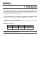
User Manual Version 1.0 SE5001A Serial Device Server 1 Introduction The SE5001A Ethernet Serial device server acts as a gateway between Ethernet (TCP/UDP) and RS-232/RS-422/RS-485 communications. The information transmitted by SE5001A is transparent to both host computers (Ethernet) and serial devices (RS-232/RS-422/RS-485).
User Manual Version 1.0 SE5001A Serial Device Server 1.
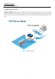
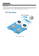
User Manual Version 1.0 SE5001A Serial Device Server 1.3 Application Connectivity TCP Server Mode:SE5001A can be configured as a TCP server in a TCP/IP Network to listen for an incoming TCP client connection to a serial device. After the connection is established between the serial device server and the host computer, data can be transmitted in both directions. This also applies to Virtual COM running in the server mode. Figure 1.
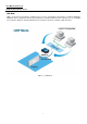
User Manual Version 1.0 SE5001A Serial Device Server TCP Client Mode SE5001A can be configured as a TCP client in TCP/IP Network to establish a connection with a TCP server in the host computer. After the connection is established, data can be transmitted between a serial device and a host computer in both directions. This also applies to Virtual COM running in the client mode. Figure 1.
User Manual Version 1.0 SE5001A Serial Device Server UDP Mode UDP is a faster but connectionless network protocol. It does not guarantee the delivery of network datagrams. SE5001A can be configured to transfer data using unicast or multicast UDP from the serial device to one or multiple host computers. Data can be transmitted between serial device and host computer in both directions. Figure 1.
User Manual Version 1.0 SE5001A Serial Device Server Tunneling Mode In the case that the serial device needs to communicate with each other without a host computer, two SE5001As can be paired together (pair connection) to communicate over TCP or UDP transparently. The serial device would be unaware of the change in the communication medium. Figure 1.
User Manual Version 1.0 SE5001A Serial Device Server 2 Getting Started 2.
User Manual Version 1.0 SE5001A Serial Device Server 2.2 Pin Assignments 2.2.
User Manual Version 1.0 SE5001A Serial Device Server 2.2.2 Ethernet Port 1. Category 5 UTP Ethernet cable. 2. RJ45 Connector. 3. RJ45 Pin Assignment Pin Assignment 568A Definition 568B Definition Pin1 Green-White Orange-White Pin2 Green Orange Pin3 Orange-White Green-White Pin4 Blue Blue Pin5 Blue-White Blue-White Pin6 Orange Green Pin7 Brown-White Brown-White Pin8 Brown Brown One can choose either 568A or 568B definition.
User Manual Version 1.0 SE5001A Serial Device Server 2.3 Buzzer “ ^ “: Beep twice “ = “: Beep off Message Description ^===^===^===^===^===^===^... (1sec) Watchdog problem, return service is required ^^^^^^^^^^^^^^^^^^^^^^^... Memory problem, return service is required ^==^========^^ (5sec) Startup OK but AP firmware is disabled ^==^========^^^ (5sec) Startup OK and AP firmware is enabled Table 1. Buzzer Message 2.
User Manual Version 1.0 SE5001A Serial Device Server 3 Software Setup SE5001A Ethernet Serial device server is shipped with default settings shown in the following table: Property Default Value IP Address 10.0.50.100 Gateway 10.0.0.254 Subnet Mask 255.255.0.0 User Name admin Password Null(leave it blank) COM 1 9600,None, 8, 1, No flow control, buffer disabled, packet delimiter timer 2ms Link 1 Type: TCP Server, Listen port 4660, Filter=0.0.0.
User Manual Version 1.0 SE5001A Serial Device Server 3.1 Configuration by Serial Manager SE5001A could be configured by Serial Manager, for more information, refer to Serial Manager’s manual. 3.2 Configuration by Telnet Utility You can use a Telnet utility to change configuration settings of SE5001A by following steps: 3.2.1. Login to the System ->Open MS-DOS command prompt window or any other telnet application ->Telnet to SE5001A using command “telnet IP_address”. (For example:”telnet 10.0.50.
User Manual Version 1.0 SE5001A Serial Device Server 1. After verifying the password, the following terminal screen appears (Figure 3.2). Figure 3.2 Main menu Note 1. If SE5001A does not receive any commands within 1 minute, Telnet connection will terminate automatically. 2. After “0. Exit” is selected; the console will ask the user to save the configurations. 3. Changes to networking parameters will take effect only SE5001A is restarted.
User Manual Version 1.0 SE5001A Serial Device Server 3.2.2. Networking Select “2” from “Input choice and enter (0~4):” to enter Networking page as following (Figure 3.4): Figure 3.4 Network settings Change network settings of the device including IP address, subnet mask, gateway IP address and SNMP information on this page. Please note that any changes made on this page won’t take effect until the device is restarted. Note: Press “ESC” key to return to the previous menu.
User Manual Version 1.0 SE5001A Serial Device Server 3.2.3. Change the Password 1. Select “3” from “Input choice and enter (0~4):” the following screen appears. (Figure 3.5) Figure 3.5 Change the Password 3.2.4. COM1 Setup Select “4” from “Input choice and enter (0~4):” the following screen appears (Figure 3.6): Figure 3.
User Manual Version 1.0 SE5001A Serial Device Server 3.2.5. Configure SE5001A as TCP server Figure 3.7 Link Mode: TCP Server Setup Type 1 (Link Mode) from “Input choice and enter (1~4):” of COM1 Type 1 (TCP Server) in the “Input choice(1~5) and enter:” Input local port in the “Please input local port:” To Enable IP filter: Input y in the “Do one want to enable IP filter(y/n)?” to enable IP Filter. Otherwise input n.
User Manual Version 1.0 SE5001A Serial Device Server 3.2.6. Configure SE5001A as TCP Client Figure 3.8 Link Mode: TCP Client Setup Type 2 in the “Input choice(1~5) and enter:“ Input destination IP in the “Please input Destination IP:” Input destination port in the “Please input Destination port:” Select TCP connection behavior: 1 for connect always, 2 for connect on serial data If 2 is selected, console will prompt for additional configurations.
User Manual Version 1.0 SE5001A Serial Device Server 3.2.7. Configure SE5001A as UDP UDP is a connectionless protocol. It is faster than TCP, but does not guarantee packet delivery to the remote host. Figure 3.9 shows how to setup UDP. Figure 3.
User Manual Version 1.0 SE5001A Serial Device Server 3.2.8. Enable / Disable Virtual COM Enable or disable Virtual COM on this page. For more information on how to setup Virtual COM on different operating systems, please refer to chapter Using Virtual COM. Figure 3.
User Manual Version 1.0 SE5001A Serial Device Server 3.2.9. Enable / Disable Pair Connection Enable or disable “Pair Connection” on this page. For more information on how to configure two serial device servers to work in pair connection, please refer to the pair connection section 3.3.13. Figure 3.
User Manual Version 1.0 SE5001A Serial Device Server 3.2.10. COM Port Setting Type 2 from “Input choice and enter (1~4):” of COM1, the following screen appears. It is possible to give the COM port alias name, set the baud rate and parity, determine number of data bit and stop bit, and the type of flow control to use here (Figure 3.12). Figure 3.
User Manual Version 1.0 SE5001A Serial Device Server 3.2.11. Emptying Serial Buffer when TCP connection is established Figure 3.13 Com Port: Enabling Serial Buffer Type 3 from “Input choice and enter (1~4):” of COM1, by default COM port serial buffer is enabled meaning that once a TCP connection is established, old serial data received from serial device before the connection will be emptied. If this option is disabled, SE5001A will keep old serial data when the connection is broken (Figure 3.13).
User Manual Version 1.0 SE5001A Serial Device Server 3.2.12. Setting Packet Delimiter Packet delimiter is a way of packaging serial data. It can prevent serial data from being truncated by packing them in the same Ethernet packet. SE5001A provides two kinds of packet delimiter: Timer and Character. The default timer is 2 ms (0ms to disable this function). This means that if SE5001A does not receive new serial data within 2ms, it will send out all the serial data in buffer in one packet over Ethernet.
User Manual Version 1.0 SE5001A Serial Device Server 3.2.13. Accept Control Command from COM port SE5001A can also accept serial control commands (RFC2217) directly from the COM port. For more details and information about this function, please contact our Technical Support. 3.2.14. Backup EEPROM to Flash Select “5” from “Input choice and enter (0~5):” the following screen should appear (Figure 3.16): Figure 3.
User Manual Version 1.0 SE5001A Serial Device Server It is also possible to modify various settings through the web server interface. To do so, please follow the steps below. 3.3.1. Log in to the System 1. After opening the web browser, ex. Microsoft IE, Firefox or any other web browser, enter the IP address of SE5001A in the URL bar. Example: http://10.0.50.100 2. The following authentication screen should appear. Enter the user name and password then click on “OK / Log in”.
User Manual Version 1.0 SE5001A Serial Device Server 3.3.2. Networking Setup Configure IP, SNMP, and alert settings on this page. Please fill in the IP information in the fields under the TCP/IP header (Figure 3.19). Alternatively, enable DHCP to obtain IP address, gateway and subnet mask from a DHCP server automatically. Figure 3.
User Manual Version 1.0 SE5001A Serial Device Server Enable SNMP and Alert Events by checking “Enable” (Figure 3.20). Fill in SNMP information in the fields under the SNMP header. Enable different Alert Events to send these events to a SNMP Trap Server. Cold/Warm Start: Triggers when the device is rebooted from the application level or physical level.
User Manual Version 1.0 SE5001A Serial Device Server 3.3.3. Security Setup Change the login password on this page (Figure 3.21). Figure 3.21 Security Setup Please enter the old password in the “Old Password” field and enter the new password in the “New Password” and the “Verified Password” fields. Then click on the “Save Configuration” to save and apply the new password. Note: Press the reset button next to the RJ-45 Jack to reset the settings back to the default value.
User Manual Version 1.0 SE5001A Serial Device Server 3.3.4. Backup EEPROM to Flash This backup function could recover settings from the Flash to the EEPROM if the settings in the EEPROM are lost. If SE5001A detects that there is an EEPROM backup in the flash. It will compare the backup values in the Flash and EEPROM. If the values do not match, it will write the backup settings in the Flash to the EEPROM. To enable this function, follow Figure 3.21 in the Security Settings.
User Manual Version 1.0 SE5001A Serial Device Server Scroll to the bottom of the page and click on “Save Configuration” button to save the changes. Go to the Application Configuration section starting from 3.3.9 to apply Virtual COM, Pair Connection, or Reverse Telnet application if applicable. Otherwise go to the COM Configuration (section 3.3.19) for serial settings directly. Figure 3.23 TCP Server Setup Note: LINK1 is associated with COM1; LINK2 is associated with COM2, and so on.
User Manual Version 1.0 SE5001A Serial Device Server 3.3.7. LINK Mode: Configure SE5001A as a TCP Client By selecting the TCP Client mode, it means that a TCP Server program should be prepared to connect to SE5001A. Figure 3.24 shows all the settings provided for the TCP Client. Click on the “COM1” link on the left hand side. Select TCP Client. Enter the preferred Destination IP and Port. This should match the IP settings of the TCP Server program.
User Manual Version 1.0 SE5001A Serial Device Server Figure 3.
User Manual Version 1.0 SE5001A Serial Device Server 3.3.8. Link Mode: Configure SE5001A in UDP SE5001A also supports connectionless UDP protocol compared to the connection-oriented TCP protocol. Please be aware that even though UDP provides better efficiency in terms of response time and resource usage, it does not guarantee data delivery. It is recommended to utilize UDP only with cyclic polling protocols where each request is repeated and independent, such as Modbus Protocol. Figure 3.
User Manual Version 1.0 SE5001A Serial Device Server 3.3.9. TCP Server Application: Enable Virtual COM SE5001A will encapsulate control packets on top of the real data when Virtual COM is enabled. This will allow the Virtual COM port in the Windows/Linux system to access SE5001A’s COM ports. The benefit of using Virtual COM is that rewriting an existing COM program to read IP packets is unnecessary. In other words, it is possible to use an ordinary serial (COM) program.
User Manual Version 1.0 SE5001A Serial Device Server 3.3.10. TCP Server Application: Enable RFC 2217 The underlying protocol of Virtual COM is based on RFC 2217, the Telnet COM Control Option. Therefore, it is possible to use RFC 2217 with SE5001A in the TCP Server mode. To do so, refer to section 3.3.9 to enable Virtual COM, so that SE5001A becomes aware of the commands. Note that there is no need to configure Virtual COM on the Operating System because Virtual COM ports would not be used. 3.3.11.
User Manual Version 1.0 SE5001A Serial Device Server 3.3.12. TCP Client Application: Enable RFC 2217 The underlying protocol of Virtual COM is based on RFC 2217, the Telnet COM Control Option. Therefore, it is possible to use RFC 2217 with SE5001A in the TCP Client mode. To do so, refer to section 3.3.11 to enable Virtual COM, so that SE5001A becomes aware of the commands. Note that there is no need to configure Virtual COM on the Operating System because Virtual COM ports would not be used. 3.3.13.
User Manual Version 1.0 SE5001A Serial Device Server 3.3.14. TCP Client Application: Configure SE5001A as a Pair Connection Slave A Pair Connection Slave (Figure 3.29) needs to pair up with a Pair Connection Master. Please setup a Pair Connection Master first before proceeding. Figure 3.29 TCP Client with Pair Connection Enabled Follow section 3.2.6 to configure SE5001A in TCP Client mode properly. Check Enable Pair Connection to enabled Pair Connection application in SE5001A.
User Manual Version 1.0 SE5001A Serial Device Server 3.3.15. TCP Server Application: Enable Reverse Telnet Reverse Telnet application is useful if a telnet program is used to connect to SE5001A and the serial interface of the SE5001A is connected to a Terminal Server. Telnet programs in Windows / Linux usually require special handshaking to get the outputs and formatting show properly. SE5001A will interact with those special commands (CR/LF commands) if Reverse Telnet is enabled. Figure 3.
User Manual Version 1.0 SE5001A Serial Device Server 3.3.16. UDP Application: Multi-Point Pair Connection It is also possible to setup pair connection in UDP mode to have more than one Pair Connection Master or Slave to communicate to each other. For example, it is possible to setup one Modbus Master and six Modbus Slaves in UDP (Figure 3.31). Note again that UDP does not guarantee data delivery and only data would be transmitted over Ethernet; other serial pings are not transmitted.
User Manual Version 1.0 SE5001A Serial Device Server 3.3.17. TCP Server Application: Multiple TCP Connections To have more than one TCP Client connecting to SE5001A in TCP Server mode, contact Atop Technical Support to obtain a special multi-connection version firmware. After the firmware is uploaded to SE5001A, the WebUI will have one additional option called “Multiple_Connections” (Figure 3.32). The Multi-Connection option will allow up to a maximum of four TCP Client connections.
User Manual Version 1.0 SE5001A Serial Device Server 3.3.18. TCP Server Application: Multi-Point TCP Pair Connections The difference between Multi-Point TCP Pair Connection and Multi-Point UDP Pair Connection is that the TCP implementation would also exchange flow controls pins of RS-232. However, the TCP Server is limited to a maximum of four connections.
User Manual Version 1.0 SE5001A Serial Device Server 3.3.19. COM Configuration Configure serial settings in this page (Figure 3.34). Note that these settings need to match the ones in the serial device. Alias Name: This field is for identification purpose only. Baud Rate: Select one of the baud rates from the dropdown box, or select Other and then enter the desired baud rate in the input box. Baud rates higher than 230400bps are not supported. Parity / Data Bits / Stop Bits: Configure them accordingly.
User Manual Version 1.0 SE5001A Serial Device Server COM Type Selection: Select between RS-232, RS-422, and RS-485. Note that RS-485 refers to 2-Wire RS-485 and RS-422 is compatible with 4-Wire RS-485. Click on “Save Configuration” button to save the changes. Figure 3.
User Manual Version 1.0 SE5001A Serial Device Server 4 Using Virtual COM Virtual COM allows remote access of serial devices over TCP/IP networks through Serial/IP Virtual COM ports that work like local native COM ports. The following figure is a Virtual COM connection diagram. (Figure 4.1) Figure 4.1 Virtual Com connection diagram 4.1 Setup of a Virtual COM Driver 4.1.1 System Requirements Windows 7, 2008, Vista, 2003, XP, 2000, NT 4.
User Manual Version 1.0 SE5001A Serial Device Server 4.1.3 Installation Run the Virtual COM setup file included in the CD or download a copy from our website to install the Virtual COM driver for the operating system. Turn off anti-virus software and try again if installation fails. At the end of the installation, please select at least one Virtual COM port from the Serial/IP Control Panel. 4.1.4 Uninstalling From Windows Start Menu select Control Panel, Add/Remove Programs.
User Manual Version 1.0 SE5001A Serial Device Server 4.2.2 Running Serial/IP in Windows Find Serial/IP Control Panel from: Start->All Programs-> Serial/IP->Control Panel In the Windows Control Panel, open the Serial/IP applet. In the Windows notification area (Figure 4.5), right click in the Serial/IP tray icon and click on Configure to open the Control Panel. Figure 4.
User Manual Version 1.0 SE5001A Serial Device Server After at least one Virtual COM port is selected, the Control Panel will show (Figure 4.7). Figure 4.7 Serial/IP Control Panel The left hand side of the Control Panel shows the list of selected Virtual COM ports. Click on Select Ports to add or remove Virtual COM ports from the list. The right hand side of the Control Panel shows the configurations of the selected Virtual COM port marked in blue. Each Virtual COM port can have its own settings.
User Manual Version 1.0 SE5001A Serial Device Server available in limited serial device servers), it is necessary to enable Use Credentials From and select Use Credentials Below from the list (Figure 4.8). Enter the Username and Password of the serial device server in the respective fields. iv. Figure 4.8 Virtual COM with Credentials v.
User Manual Version 1.0 SE5001A Serial Device Server Figure 4.
User Manual Version 1.0 SE5001A Serial Device Server Exceptions: Figure 4.10 Virtual COM Timeout Exception a. If the exclamation mark begins with Warning: timeout trying x.x.x.x (Figure 4.10), recheck the Virtual COM IP and Port configuration or the PC’s network configuration.
User Manual Version 1.0 SE5001A Serial Device Server Figure 4.11 Virtual COM Raw Connection Exception b. If there is a check with Raw Connection Detected and an exclamation mark with Client not licensed for this server (Figure 4.11), enable Virtual COM in the serial device server.
User Manual Version 1.0 SE5001A Serial Device Server Figure 4.12 Virtual COM License Exception c. If there is a check with Telnet Protocol Detected and an exclamation mark with Client not licensed for this server (Figure 4.12), this means that there is a licensing issue between the serial device server and Serial/IP. Please contact Atop technical support to obtain the correct Virtual COM software.
User Manual Version 1.0 SE5001A Serial Device Server Figure 4.13 Virtual COM Credentials Exception d. If the exclamation mark begins with Server requires username/password login (Figure 4.13), it means VirtualCOM Authentication in the serial device server is enabled, but credentials in the Serial/IP is not enabled.
User Manual Version 1.0 SE5001A Serial Device Server Figure 4.14 Virtual COM Username Password Exception e. If the exclamation mark begins with Username and/or password incorrect (Figure 4.14), this means the wrong username and/or password was entered and the authentication failed.
User Manual Version 1.0 SE5001A Serial Device Server Figure 4.15 Virtual COM Credentials Exception f. If the exclamation mark begins with No login/password prompts received from server (Figure 4.15), it means credentials in the Serial/IP is enabled, but VirtualCOM Authentication in the serial device server is not enabled.
User Manual Version 1.0 SE5001A Serial Device Server 4.4 Using Serial/IP Port Monitor 4.4.1. Opening the Port Monitor The Serial/IP Port Monitor can be opened by: Start->All Programs-> Serial/IP->Port Monitor Double click the Serial/IP tray icon in the Windows notification area (Figure 4.5). In the Windows notification area (Figure 4.5), right click in the Serial/IP tray icon and click on Port Monitor to open the Port Monitor.
User Manual Version 1.0 SE5001A Serial Device Server 4.4.3. The Trace Panel Figure 4.17 Port Monitor Trace Panel The Trace panel provides a detailed, time-stamped, real-time display of all Serial/IP COM ports operations (Figure 4.17). Click on Enable Trace to start logging Virtual COM communication. Click on File->Save As and send the log to Atop for analysis If problems arises with Virtual COM.
User Manual Version 1.0 SE5001A Serial Device Server 4.5 Serial/IP Advanced Settings In the Serial/IP Control Panel, Click on the Advanced button to open Advanced Settings window (Figure 4.18). Click on Use Default Settings to load the default settings. Figure 4.
User Manual Version 1.
User Manual Version 1.0 SE5001A Serial Device Server 4.6 Using Serial/IP with a Proxy Server The Serial/IP Redirector supports TCP network connections made through a proxy server, which may be controlling access to external networks (such as the Internet) from a private network that lacks transparent IP-based routing, such as NAT. Find Proxy Server settings from the Advanced Settings windows and switch to the Proxy Server tab (Figure 4.19) Figure 4.
User Manual Version 1.0 SE5001A Serial Device Server 5 Diagnostics There are several ways to can check the status and availability of the serial device server. 5.1 Using Standard Ping Command From the Windows Start menu, select Run and type in “ping ”. If the serial device server can receive ping requests sent from the host, it will reply to the ping message (Figure 6.1). If the ping request cannot reach the serial device server, timed out message will show (Figure 6.2). Figure 6.
User Manual Version 1.0 SE5001A Serial Device Server 5.2 Using Serial Manager Configuration Utility Use Serial Manager configuration utility that comes with the product CD or download from Atop website to check on the status of the serial device server. The status and version can be read from the tool. For example, ‘S’ means that COM1 is in TCP Server mode and is not connected to a TCP Client (Figure 6.3). ‘A’ means that COM1 is in server mode and is connected to a TCP Client. Figure 6.
User Manual Version 1.0 SE5001A Serial Device Server Appendix Specifications Network Interface Ethernet 1x RJ-45 IEEE802.3 10/100Mbps, Auto MDI/MDI-X Serial Interface Connector D-Sub9 RS-232/422/485 software selectable 3.81mm TB5 RS-232/422/485 software selectable (TB models) Ports 1 Port Baud Rate 1200~230Kbps Data Bits 7,8 Stop Bits 1,2 Flow Control None, Xon/Xoff, RTS/CTS Power Characteristics Input Voltage 9VDC-48VDC Input Current(9VDC) 0.30A Power Consumption Approx. 2.
User Manual Version 1.0 SE5001A Serial Device Server Link Modes TCP Server 4 connections, Virtual COM, or Reverse Telnet TCP Client Single destination or Virtual COM UDP Up to 4 ranges of IPs Upgrade System Firmware Firmware is available for download on Atop website: http://www.atop.com.tw. Subscribe to our RSS system http://www.atop.com.tw/en/rss.php to receive our latest firmware updates automatically.
User Manual Version 1.0 SE5001A Serial Device Server Figure B.2 Dapdl.cfg Opened with an Editor 7. File->Save and File->Exit the text editor. 8. Enter the admin as the userid and the password of SE5001A. If a password is not set, press enter. The batch file will upgrade the system firmware. SE5001A will restart automatically after the new firmware is uploaded. Figure B.
User Manual Version 1.0 SE5001A Serial Device Server 9. Repeat the process above again for kernel or AP firmware if necessary. Note: After the upgrading process finishes, SE5001A will program the flash memory and buzzer beeps 6 times then restarts. Normally, it takes around 10 seconds to complete the programming process. If an error occurs during the programming process, SE5001A will clear the corresponding memory and the system remains intact of what it was.
User Manual Version 1.0 SE5001A Serial Device Server Emergency Firmware Recovery The AP (application program) firmware of SE5001A can be disabled to restore the device to the proper firmware in case an incompatible firmware was downloaded and the system crashes while loading the AP. To disable the AP firmware and prevent it from executing, please do the following. 1. Power off the device. 2. While the reset button is pressed, power on the device. 3.