SE5404D Series 4-Port DIN-Rail Serial Device Server User’s Manual Version 1.3 May 2012 Tel: 886-3-5508137 Fax: 886-3-5508131 http://www.atop.com.
User manual Version 1.3 4-Port DIN-Rail Serial Device Server SE5404D IMPORTANT ANNOUNCEMENT The information contained in this document is the property of Atop Technologies, Inc. and is supplied for the sole purpose of the operation and maintenance of products of Atop Technologies, Inc.
User manual Version 1.3 4-Port DIN-Rail Serial Device Server SE5404D Thank you for purchasing SE5404D Serial Device Server product. This document intends to provide customers with brief descriptions about the product and to assist customers to get started. For detail information and operations of the product, please refer to the product user’s manual in the product CD or diskette.
User manual Version 1.3 4-Port DIN-Rail Serial Device Server SE5404D Contents 1. INTRODUCTION .............................................................................................................................. 7 1.1 PACKAGING ...............................................................................................................................................7 1.2 APPLICATION CONNECTIVITY ....................................................................................................
User manual Version 1.3 4-Port DIN-Rail Serial Device Server SE5404D 3.2.20 RESTART SYSTEM ................................................................................................................................29 3.3 WEB CONFIGURATION ..............................................................................................................................30 3.3.1 LOGIN TO SYSTEM ....................................................................................................................
User manual Version 1.3 4-Port DIN-Rail Serial Device Server SE5404D 4.1.1 Pre-installation requirements.......................................................................................................56 4.1.2 Cautions on Use ............................................................................................................................56 4.1.3 Limitation .....................................................................................................................................
User manual Version 1.3 4-Port DIN-Rail Serial Device Server SE5404D A.4.1 Buzzer ........................................................................................................................................... 74 APPENDIX B: UPGRADE SYSTEM FIRMWARE ..................................................................................... 75 B.2 CRITICAL ISSUES OF UPGRADING .................................................................................................................75 B.
User manual Version 1.3 4-Port DIN-Rail Serial Device Server SE5404D 1. Introduction Many industrial and Commercial devices equipped with slow serial communication ports—RS-232, RS-485, and RS-422—are limited in their transmission distance of 15 m. Examples of these devices are PLC controllers, card readers, display signs, security controls, CNC controller, etc. ATOP Technologies has overcome the limit with a family of SE5404D Series Serial Device Servers.
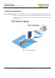
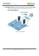
User manual Version 1.3 4-Port DIN-Rail Serial Device Server SE5404D 1.2 Application Connectivity TCP Server Mode:SE5404D can be configured as a TCP server on TCP/IP Network to wait for other applications (clients) in host computer to establish a connection with the serial device. After the connection is established between serial device and host computer, data can be transmitted in both directions Figure 1.1. Figure 1.1 TCP Server Mode Copyright © 2011 Atop Technologies, Inc. All rights reserved.
User manual Version 1.3 4-Port DIN-Rail Serial Device Server SE5404D TCP Client Mode:SE5404D can be configured as a TCP client on TCP/IP Network to actively establish a connection with other applications(server) in host computer. After the connection is established, data can be transmitted between serial device and host computer in both directions (Figure 1.2). Figure 1.2 TCP Client Mode Copyright © 2011 Atop Technologies, Inc. All rights reserved. Designed in Taiwan.
User manual Version 1.3 4-Port DIN-Rail Serial Device Server SE5404D UDP Mode:UDP is a faster but non-guaranteed datagram delivery protocol.SE5404D can be configured as a UDP mode on TCP/IP Network to establish a connection using unicast data from the serial device to one or multiple host computers (Figure 1.3) Vice versa is also true. Figure 1.
User manual Version 1.3 4-Port DIN-Rail Serial Device Server SE5404D Figure 1.4 Tunneling Mode Copyright © 2011 Atop Technologies, Inc. All rights reserved. Designed in Taiwan.
User manual Version 1.3 4-Port DIN-Rail Serial Device Server SE5404D 2. Hardware Setup NOTE: 1. SE5404D (RS-232/422/485 DB9 without isolation ), 2. SE5404D-TB (RS422/485 TB5 with isolation) 3. SE5404D-Sis (RS422/485 TB5 with isolation) 4. You can press the Default button of SE5404D to reset the settings to the default value Figure 2.1 Show the names of SE5404D components. Figure 2.1 Front Panel Interfaces Copyright © 2011 Atop Technologies, Inc. All rights reserved. Designed in Taiwan.
User manual Version 1.3 4-Port DIN-Rail Serial Device Server SE5404D Figure 2.2 7-Pin Terminal Block DC Power on Top Plate Attention This product is intended to be grounded properly. Please do so via the Frame Ground. 2.
User manual Version 1.3 4-Port DIN-Rail Serial Device Server SE5404D Blinking AP firmware is running normally 2.2 Installation Procedures Step 1: Connect SE5404D to power source Step 2: Connect SE5404D to the Ethernet network. Use a standard straight-through or cross-over Ethernet cable Always make sure the PC is on the same network subnet as SE5404D. Step 3: Connect SE5404D’s serial port to a serial device. Step 4: Mount SE5404D to a Din Rail.
User manual Version 1.3 4-Port DIN-Rail Serial Device Server SE5404D 3. Software Setup SE5404D Serial Device Server is shipped with default settings shown in the following table: Property LAN1 LAN2 Default Value IP Address 10.0.50.100 Gateway 10.0.0.254 Subnet Mask 255.255.0.0 IP Address 192.168.1.1 Gateway 192.168.1.254 Subnet Mask 255.255.255.
User manual Version 1.3 4-Port DIN-Rail Serial Device Server SE5404D 3.1 Configuration by Serial Manager Utility 3.1.1.Static IP Figure 3.1 Configure by Serial Manager Utility Figure 3.2 Static IP setup dialog window 3.1.2 DHCP client (Dynamic IP) A DHCP server can automatically assign the IP address and network settings. SE5404D supports the DHCPclient function.
User manual Version 1.3 4-Port DIN-Rail Serial Device Server SE5404D Figure 3.3 Serial Manager Utility Auto IP 3.2 Telnet Configuration One may also use Telnet utility to change configuration settings. Open MS-DOS command prompt window or other telnet tools Enter the “Telnet IP_address” (For example, Telnet 10.0.50.100). The system will prompts for a user and password, the default User is “admin” and password is Null (Leave it blank). Figure 3.
User manual Version 1.3 4-Port DIN-Rail Serial Device Server SE5404D Figure 3.5 Main menu of Telnet Note: If the Serial Server does not receive any command within 3 minutes, Telnet will be terminated automatically. 3.2.1 General Information Operation: Main[1]Overview This system overview window gives the general information on Ethernet, MAC address, kernel and AP version. Figure 3.6 Overview Information by Telnet Copyright © 2011 Atop Technologies, Inc. All rights reserved. Designed in Taiwan.
User manual Version 1.3 4-Port DIN-Rail Serial Device Server SE5404D 3.2.2 Networking Configuration Operation: Main[2]Networking This section allows for changes in IP address, subnet mask, gateway IP address and SNMP information. Please note that setting changes will not take effect until the device is restarted. Figure 3.7 Network Settings by Telnet Note: Press “ESC” key to return to the previous menu 3.2.
User manual Version 1.3 4-Port DIN-Rail Serial Device Server SE5404D Operation: Main[2]Networking[2]LAN 2 Settings Enter “LAN 2 settings”, and there is all information at this section about IP address, gateway, subnet mask and IP mode (static/DHCP) of LAN 2. Figure 3.9 LAN 2 Settings by Telnet 3.2.4 DNS Settings Operation: Main[2]Networking[3]DNS Settings Serial Server is able to configure the DNS1 or DNS2 Server IP Address manually.
User manual Version 1.3 4-Port DIN-Rail Serial Device Server SE5404D 3.2.5 SNMP Settings Operation: Main[2]Networking[4]SNMP Settings Serial Server allows the user to Enable or Disable the SNMP function by choose the “[4] SNMP: Disable” and select “Enable” to enable the SNMP operation. The changes will effective immediately. Serial Server supports basic SNMP function about system MIB (Management Information Base).
User manual Version 1.3 4-Port DIN-Rail Serial Device Server SE5404D 3.2.7 TCP Server for Link Mode Operation: Main [3]COM Port Setting[1-16]Select Port[1]Link Mode[1]TCP Server TCP Server mode is default setting for Link mode of serial settings, and it can be configured in a TCP server mode on an Ethernet Network to waiting for the host computers to establish a connection with the serial device (the client).
User manual Version 1.3 4-Port DIN-Rail Serial Device Server SE5404D Figure 3.14 TCP Client for Link mode 3.2.9 UDP Link Mode Operation: Main [3]COM Port Setting[1-16]Select Port[1]Link Mode[3]UDP Serial Server can be configured in a UDP mode to establish connection using uni-cast or broadcast the data from the serial device to one or multiple host computers. Vice versa is also true.
User manual Version 1.3 4-Port DIN-Rail Serial Device Server SE5404D 3.2.10 Serial Settings Operation: Main [3]COM Port Setting[1-16]Select Port[2]Com Settings Here one may configure baud rate, parity, data bit, stop bit, flow control, and UART mode as defined by the user. Figure 3.16 Serial Setting by Telnet 3.2.12 Alert Settings There are two subsystem settings include E-mail and Alert Event. Copyright © 2011 Atop Technologies, Inc. All rights reserved. Designed in Taiwan.
User manual Version 1.3 4-Port DIN-Rail Serial Device Server SE5404D Figure 3.19 Alert Settings by Telnet 3.2.13 Configuring E-mail Operation: Main [4]Alert Settings[1]E-mail Settings One may configure the “Sender’s E-mail address” that it should have on the SMTP server (Mail Server) where allowed to sent out the email by sender’s E-mail address. The SE5404D allow to definite the receiver up to 5.
User manual Version 1.3 4-Port DIN-Rail Serial Device Server SE5404D Figure 3.21 Configuring Mail Server by Telnet 3.2.14 Configuring Alert Event Operation: Main [4]Alert Settings[2]Alert Event Choose the Alert event to configure SE5404D Series to send the alert notification by E-Mail or SNMP Trap (See Fig. 3.22). Figure 3.22 Configuring Alert Event by Telnet Copyright © 2011 Atop Technologies, Inc. All rights reserved. Designed in Taiwan.
User manual Version 1.3 4-Port DIN-Rail Serial Device Server SE5404D 3.2.15 System Configuration Operation: Main [5]System Figure 3.23 Security settings by Telnet 3.2.16 Link State Operation: Main [5]System[1]Link State Link State is display information by Link mode (TCP Server, TCP Client and UPD) and status of each connection for all serial port. Figure 3.24 Display Link State by Telnet Copyright © 2011 Atop Technologies, Inc. All rights reserved. Designed in Taiwan.
User manual Version 1.3 4-Port DIN-Rail Serial Device Server SE5404D 3.2.17 Time Settings Operation: Main [5]System[2]Time One may configure time to Manual Settings or NTP services. The changed will take effect immediately when saved successful. Figure 3.25 Time settings by Telnet 3.2.18 Security Settings Operation: Main[5]System[3]Security SE5404D serials allow one to change the access methods to protect it against intrusion. Figure 3.
User manual Version 1.3 4-Port DIN-Rail Serial Device Server SE5404D 3.2.19 Restoring Factory Default Operation: Main [6]Set to Default Choose this menu to restore Serial Server’s settings to Factory Default Settings. Figure 3.27 Restore Factory Default by Telnet 3.2.20 Restart System Operation: Main [7]Restart Choose this menu to restart the SE5404D series. Figure 3.28 Restart System by Telnet Copyright © 2011 Atop Technologies, Inc. All rights reserved. Designed in Taiwan.
User manual Version 1.3 4-Port DIN-Rail Serial Device Server SE5404D 3.3 Web Configuration 1. Make sure your PC is located on the same network sub-net as SE5404D 2. Open a web browser, then Enter in the IP address of SE5404D to be configured. Default user name is admin and default password is null (leave it blank). 3. SE5404D’s network, link mode and COM ports settings can be configured in different web pages. 4. Click “Save Configuration” to save settings. 5.
User manual Version 1.3 4-Port DIN-Rail Serial Device Server SE5404D Figure 3.20 Overview by Web page Device Information SE5404D Serial Server’s displays system information Kernel version and AP version. The information are read only and attributed from another setting page or system status (See Fig. 3.21) Figure 3.21 Device Information by Web page Networking information Networking information fields are displayed both ‘LAN 1 and LAN 2’ s information on overview page.
User manual Version 1.3 4-Port DIN-Rail Serial Device Server SE5404D Figure 3.22 Network Information by Web page 3.3.3 Network Configuration There are four items allowed to change on Network page in which include LAN 1, LAN 2, DNS and SNMP Information. Copyright © 2011 Atop Technologies, Inc. All rights reserved. Designed in Taiwan.
User manual Version 1.3 4-Port DIN-Rail Serial Device Server SE5404D Figure 3.23 Network Configuration by Web page 3.3.4 LAN 1 Settings Click on the “Network” link and the following screen shall appear. Fill in LAN 1 IP information on LAN 1 TCP/IP field. Alternatively, one may activate DHCP client function by checking on “Obtain an IP automatically”. Copyright © 2011 Atop Technologies, Inc. All rights reserved. Designed in Taiwan.
User manual Version 1.3 4-Port DIN-Rail Serial Device Server SE5404D Figure 3.24 LAN 1 Setting by Web page 3.3.5 LAN 2 Settings Click on the “Network” link and the following screen shall appear. Fill in LAN 2 IP information on LAN 2 settings fields. Alternatively, one may activate DHCP client function by checking on “Obtain an IP automatically” field to obtain IP address, gateway and subnet mask from DHCP server automatically. Figure 3.25 LAN 2 Setting by Web page 3.3.
User manual Version 1.3 4-Port DIN-Rail Serial Device Server SE5404D Figure 3.26 DNS Setting by Web page 3.3.7 SNMP Settings Click on the “Network” link and the following screen shall appear. Fill in SNMP information on third field. Alternatively, to settings SysName, SysLocation, SysContact fields and one may configure by Checking on “Enable SNMP” field. Fill in Read Community, Write Community, SNMP Trap Server information on SNMP Settings fields.
User manual Version 1.3 4-Port DIN-Rail Serial Device Server SE5404D 3.4 COM Port Configuration Figure 3.28 COM Port Configuration by Web page 3.4.1 TCP Server for Link Mode TCP Server mode is the default Link mode of serial settings, and it can wait for connecting requirement from remote host PC which “serial-to IP” tool installed or counter-pair SE5404D Serial servers in tunneling mode.
User manual Version 1.3 4-Port DIN-Rail Serial Device Server SE5404D to TCP Client mode IP and port equal to SE5404D A COM2’s settings (Default Destination IP=10.10.50.100, Default Destination Port = 4661). Max Connections (default=1): This option is used if you need to receive data from different hosts simultaneously. When set to 1, only a single host may open the TCP connection to the serial port. When set to 2 or greater, up to the specified number of hosts may open this port at the same time.
User manual Version 1.3 4-Port DIN-Rail Serial Device Server SE5404D Figure 3.29 TCP Server in Link mode Note: Enable Virtual COM mode if the remote site PC’s “Serial to IP” tool installed 3.4.2 TCP Client for Link Mode One may enter destination IP & port (default: 4660) to establish connection of counter-pair (remote) host (For example, another serial server, or PC for data-collection). Serial Server can support two destination hosts simultaneously.
User manual Version 1.3 4-Port DIN-Rail Serial Device Server SE5404D Figure 3.30 TCP Client in Link mode 3.4.3 UDP for Link Mode UDP is a fast but non-guaranteed datagram delivery protocol. Serial Server can be configured in a UDP mode on a TCP/IP Network to establish a connection, using uni-cast or broadcast data to and from a serial device to one or multiple host computer,.
User manual Version 1.3 4-Port DIN-Rail Serial Device Server SE5404D Figure 3.31 UDP in Link mode Note: UDP mode doesn’t support Virtual COM mode yet 3.4.5 Serial Settings This filed can configure serial parameters for Serial Server.
User manual Version 1.3 4-Port DIN-Rail Serial Device Server SE5404D Figure 3.32-1 Serial Settings by Web page 3.4.6 Advanced Settings Figure 3.32-1 Advanced Settings by Web page Time out for receiving TCP data (Default: Disabled): This field specifies how long the serial device server will wait for a response to “keep alive” packets before closing the TCP connection. The serial device server checks Copyright © 2011 Atop Technologies, Inc. All rights reserved. Designed in Taiwan.
User manual Version 1.3 4-Port DIN-Rail Serial Device Server SE5404D connection status by sending periodic “keep alive” packets. If the remote host does not respond to the packet within the time specified in this field, the serial device server will force the existing TCP connection to close. If this setting is set to 0, the TCP connection will remain open even if there is no response to the “keep alive” packets.
User manual Version 1.3 4-Port DIN-Rail Serial Device Server SE5404D Response interval timeout (Default: 1000ms): This option only work in Request & Response Mode. When TCP data is received (request) and passed to Serial side, the device will wait for the set time before transferring another TCP data if the Serial side did not receive any data (response).
User manual Version 1.3 4-Port DIN-Rail Serial Device Server SE5404D Figure 3.33 Alert settings by Web page 3.4.8 Configuring E-mail Operation: AlertE-mail Click on the “E-mail” link and the following screen shall appear One may configure the “Sender’s E-mail address” that it should have on the SMTP server (Mail Server) where allowed to sent out the email by sender’s E-mail address. The SE5404D allow to definite the receiver up to 5.
User manual Version 1.3 4-Port DIN-Rail Serial Device Server SE5404D Figure 3.34 Configuring E-mail by Web page One may configure Mail Server and checking on “My mail server requests authentication” field to obtain User name and Password. Figure 3.35 Configuring Mail Server by Web page 3.4.
User manual Version 1.3 4-Port DIN-Rail Serial Device Server SE5404D Figure 3.36 Configuring Alert Event by Web page 3.5 System Configuration There are six subsystem settings for system configuration including Link State, Time, Security, Set to Default and Restart. Copyright © 2011 Atop Technologies, Inc. All rights reserved. Designed in Taiwan.
User manual Version 1.3 4-Port DIN-Rail Serial Device Server SE5404D Figure 3.37 System Configuration by Web page 3.5.1 Link State information Operation: SystemLink State Link State is display information by Link mode (TCP Server, TCP Client and UPD) and status of each connection for all serial port. Figure 3.38 Link State Information by Web page 3.5.2 Log Settings Operation: SystemLog Setting Copyright © 2011 Atop Technologies, Inc. All rights reserved. Designed in Taiwan.
User manual Version 1.3 4-Port DIN-Rail Serial Device Server SE5404D Figure 3.39 System Log Setting WebUI Enable Log Event to Flash: This would write log events to the local flash. Log Level: 3 (Currently we only allow this level) Enable Syslog Server: Enabling this option would allow you to send Syslog events to a remote Syslog server. Syslog Server IP: Please specify the remote Syslog Serve IP. Syslog Server Service Port: Please specify the remote Syslog Serve Port. Figure 3.
User manual Version 1.3 4-Port DIN-Rail Serial Device Server SE5404D Syslog Server IP: Please specify the remote Syslog Serve IP. Syslog Server Service Port: Please specify the remote Syslog Serve Port. 3.5.3 System Log Operation: SystemSystem Log Figure 3.41 COM Log Setting WebUI 3.5.4 COM Log Operation: SystemCOM Log Figure 3.42 COM Log Setting WebUI You can select which COM to be displayed. The first three logs were set to log data length and the last two logs were set to log data content.
User manual Version 1.3 4-Port DIN-Rail Serial Device Server SE5404D Figure 3.43 Time Settings by web page 3.5.6 Security Configuration Operation: SystemSecurity Click on the “Security” link and the following screen shall appear Copyright © 2011 Atop Technologies, Inc. All rights reserved. Designed in Taiwan.
User manual Version 1.3 4-Port DIN-Rail Serial Device Server SE5404D Figure 3.44 Security Configuration by Web page. Enter the old password on “Old Password” field; enter the new password on “New Password” and the “Verified Password” fields, and then click on “Save Configuration” to update the password. Copyright © 2011 Atop Technologies, Inc. All rights reserved. Designed in Taiwan.
User manual Version 1.3 4-Port DIN-Rail Serial Device Server SE5404D Figure 3.45 Change password by Web page Note: One may press the reset key on product to reset password to the default value SE5404D serials allow one to change the access methods to protect it against intrusion. Figure 3.46 Security Configuration by Web page. 3.5.7 Import/Export Operation: SystemImport/Export Please select a setting file to be imported or a file path for the settings to be exported on the WebUI.
User manual Version 1.3 4-Port DIN-Rail Serial Device Server SE5404D Figure 3.47 Import/Export WebUI 3.5.8 Restore Factory Default Operation: System Set to Default One may click on “set to default and restart” button to restore Serial Server’s settings to Factory Default Settings. Copyright © 2011 Atop Technologies, Inc. All rights reserved. Designed in Taiwan.
User manual Version 1.3 4-Port DIN-Rail Serial Device Server SE5404D Figure 3.48 Restore Factory Default by Web page 3.5.9 Restart System Operation: System Restart One may press “Restart” button to restart the SE5404D series. The web page will be refreshing after it reboot. Copyright © 2011 Atop Technologies, Inc. All rights reserved. Designed in Taiwan.
User manual Version 1.3 4-Port DIN-Rail Serial Device Server SE5404D Figure 3.49 Restart System by Web page Copyright © 2011 Atop Technologies, Inc. All rights reserved. Designed in Taiwan.
User manual Version 1.3 4-Port DIN-Rail Serial Device Server SE5404D 4. Using Virtual COM Virtual COM driver mode for windows converts COM data to LAN data to control the COM port on a SE5404D via the LAN. By creating virtual COM ports on the PC, the Virtual COM driver redirects the communications from the virtual COM ports to an IP address and port number on a SE5404D that connects the serial line device to the network. The following figure is Virtual COM connection diagram. (ref Figure 4.1) Figure 4.
User manual Version 1.3 4-Port DIN-Rail Serial Device Server SE5404D 4.1.4 Installation Make sure you have turned off all anti-virus software before beginning the installation. Run the Virtual COM setup file included in the CD to install Virtual COM driver for your operating system. In the end of the installation, please select one or two COM ports to become the Virtual COM ports. 4.1.5 Uninstalling 1. From Windows Start menu select Setting, Control Panel, Add/Remove Programs. 2.
User manual Version 1.3 4-Port DIN-Rail Serial Device Server SE5404D 4.2.2 Run Serial/IP on PC In the Window Start Menu, go to “Programs”, select “Serial/IP” and select “Control Panel”. When “Select Port” windows pop-up, please select the serial port you want to configure. Then the configuration window will appear. (ref Figure 4.4) Figure 4.4 Serial/IP configuration At the right side of Figure 4.4 is a sample Virtual COM Control Panel window.
User manual Version 1.3 4-Port DIN-Rail Serial Device Server SE5404D the settings you have provided. If the Log display does not show errors, click the Use Settings button in the wizard, which makes the recommended settings effective and returns you to the Control Panel to continue with the following steps.(ref Figure 4.5) Figure 4.5 Configuration Wizard 6. For Connection Protocol, the setting must match the TCP/IP protocol that the serial server supports.
User manual Version 1.3 4-Port DIN-Rail Serial Device Server SE5404D 5. SNMP Setup 5.1 SNMP Network Management Platform SE5404D is an SNMP device that allows many popular SNMP Network management platforms such as HP OpenView and SunNet Manager to conduct on the Serial Manager Utility. Depending on the network management tools you are using, device (SE5404D) information can be collected from running the management tools including IP address, DNS name, system descriptions and NIC information etc. 5.
User manual Version 1.3 4-Port DIN-Rail Serial Device Server SE5404D Click on “OK” and the following dialog box appears. It displays the searching progress(Figure 5.2). Figure 5.2 Discovering network 2. When the search is completedd, NetworkView will display the devices found in the main window, as shown in the following diagramFigure 5.3. Figure 5.3 NetworkView- main window 3.
User manual Version 1.3 4-Port DIN-Rail Serial Device Server SE5404D 6. Start Writing Ones Own Applications Before you start writing ones host applications or programs to interact with SE5404D, please make sure one have done the following. 6.1 Preparing The System 1. Properly connect SE5404D hardware including power, Ethernet and serial cable 2.
User manual Version 1.3 4-Port DIN-Rail Serial Device Server SE5404D Figure 6.1 TCP test sample program in Visual B 6.2.2 TCPTEST2 in Visual C Enter in the following command in the command line prompt(Figure 6.2): TCPTEST2 IP_Address Port_Number Figure 6.2 TCP test sample program in Visual C The command tcptest2 10.0.50.100 4660 brings you to connect to a TCP server of IP address 10.0.50.
User manual Version 1.3 4-Port DIN-Rail Serial Device Server SE5404D 7. Diagnostics There are several ways you can check on the status and availability of SE5404D. 7.1 Use Standard TCP/IP Utility ping Command From Windows Start menu, select Run and Enter in “ping ”(Figure 7.1). If the connection is established, the Reply messages are displayed, otherwise it will indicate Request timed out. Figure 7.1 Standard TCP/IP utility ping command 7.
User manual Version 1.3 4-Port DIN-Rail Serial Device Server SE5404D Figure Serial Manager configuration utility 7.3 Use TCPTEST.EXE or TCPTEST2.EXE Sample Program Use sample programs TCPTEST.EXE and TCPTEST2.EXE that comes with the product CD or diskette to check on the status of SE5404D. Please refer to chapter 6.2 to run the sample programs. Copyright © 2011 Atop Technologies, Inc. All rights reserved. Designed in Taiwan.
User manual Version 1.3 4-Port DIN-Rail Serial Device Server SE5404D Appendix A: Specifications Specifications Ethernet Compliance IEEE802.
User manual Version 1.3 4-Port DIN-Rail Serial Device Server SE5404D Indicator COM, LAN, RUN EMC CE Class A, FCC Class A Protection IP50 Rated IEC/EN60529 Vibration IEC60068-2-64 Shock IEC60068-2-27 Free-fall IEC60068-2-32(ISTA Test Procedure 2A) Operating -40℃~85℃(-40°F ~176°F) Storage -40℃~85℃(-40°F ~185°F) Humidity 5%~95% Non-condensing (WxHxD) 53.4mm x 145.7mm x 119.
User manual Version 1.3 4-Port DIN-Rail Serial Device Server SE5404D A.3.1.1 SE5404D Front Panel A.3.1.2 SE5404D Side View Copyright © 2011 Atop Technologies, Inc. All rights reserved. Designed in Taiwan.
User manual Version 1.3 4-Port DIN-Rail Serial Device Server SE5404D Copyright © 2011 Atop Technologies, Inc. All rights reserved. Designed in Taiwan.
User manual Version 1.3 4-Port DIN-Rail Serial Device Server SE5404D A.3.1.3 SE5404D Top View Copyright © 2011 Atop Technologies, Inc. All rights reserved. Designed in Taiwan.
User manual Version 1.3 4-Port DIN-Rail Serial Device Server SE5404D A.3.1.4 SE5404D Rear and Mounting View Copyright © 2011 Atop Technologies, Inc. All rights reserved. Designed in Taiwan.
User manual Version 1.3 4-Port DIN-Rail Serial Device Server SE5404D A.3.2.
User manual Version 1.3 4-Port DIN-Rail Serial Device Server SE5404D A.3.2.2 Terminal Block Pin Assignments The pin assignments of Terminal Block connector on SE5404D-TB / SE5404D-Sis is shown in the following table: RS-422/4-Wire RS-485 2-Wire RS-485 Full Duplex Half Duplex for SE5404D-TB / SE5404D-Sis For SE5404D-TB / SE5404D-Sis Pin# 1 T+ NC 2 T- NC 3 R+ Data+ 4 R- Data- 5 SG (Signal Ground) SG (Signal Ground) A.3.3.1 Ethernet Port (RJ-45) 1. Category 5 UTP cable, 8 core wires.
User manual Version 1.3 4-Port DIN-Rail Serial Device Server SE5404D Pin4 Blue Blue Pin5 Blue-White Blue-White Pin6 Orange Green Pin7 Brown-White Brown-White Pin8 Brown Brown You can choose either 568A or 568B definition. If you want to make a crossover cable, you should use 568A and 568B definition respectively in each terminal of a UTP cable. A.3.4.
User manual Version 1.3 4-Port DIN-Rail Serial Device Server SE5404D Appendix B: Upgrade System Firmware After the new version of firmware is released, customers can download from www.Atop.com.tw. After you download the firmware, please follow these instructions listed below. B.1 Upgrade Procedure Please follow Appendix C if you want to use Serial Manager to upgrade firmware.
User manual Version 1.3 4-Port DIN-Rail Serial Device Server SE5404D restarting. It takes around 30 seconds to complete the programming process. If an error occurs during the programming process, SE5404D will clear the corresponding memory and the system remains the same before the process. B.3 Error Messages Firmware upgrade may not be successful if errors occur during the process.
User manual Version 1.3 4-Port DIN-Rail Serial Device Server SE5404D Appendix C: Using Serial Manager Utility C.1. Serial Manager utility Introduction Serial Manager utility, developed by ATOP, is a special tool for device management and configuration. It can realize the daily management on various ATOP network devices for address search, device positioning, parameter configuring, and firmware downloading. Note that EW5302 is used to demonstrate the functionality of Serial Manager instead of SE5404D. C.2.
User manual Version 1.3 4-Port DIN-Rail Serial Device Server SE5404D current search method. To select the search methods, users click the “Search” on the main menu which is shown below. Alternatively, users can select by clicking the Rescan button on the toolbar as below. Broadcast Search Once “Broadcast Search” is selected, a box will pop up as below. The user may type in or select different broadcast address based on the requirement. Copyright © 2011 Atop Technologies, Inc. All rights reserved.
User manual Version 1.3 4-Port DIN-Rail Serial Device Server SE5404D Search by IP address Once “Search by IP Address” is selected, an interface will pop up as below. Here user may have two options: Select an IP address to search or Search device in the range of IP address. Search by MAC Address If “Search by MAC Address” is selected, another box will pop up as below.
User manual Version 1.3 4-Port DIN-Rail Serial Device Server SE5404D Rescan Once the user click the “Rescan” button on the toolbar, the Serial Manager utility shall re-search devices by using the current search way. C.3.2. Firmware This function is applied to downloading a firmware into the selected device.
User manual Version 1.3 4-Port DIN-Rail Serial Device Server SE5404D And then the user can select and download the required firmware from the disk, as shown in the figure below. The user can also select several same devices at one time, and realize the firmware updating for them by selecting Apply for all selected devices have same model. Copyright © 2011 Atop Technologies, Inc. All rights reserved. Designed in Taiwan.
User manual Version 1.3 4-Port DIN-Rail Serial Device Server SE5404D C.3.3. Configuration This function is for device configuration to set up parameters, to import and to export the parameters, and to set up some options. Here is the list of configurations: “Network”, “SNMP”, “COM Port”, “Locate”, “Reset”, “Import Setting”, “Export Setting”, “Virtual COM”, “Config by browser” and “Options.
User manual Version 1.3 4-Port DIN-Rail Serial Device Server SE5404D Network The user can modify the IP address of any selected device, shown as the figure below. You can statically assign IP address, Subnet mask, and Gateway. Optionally, you can set up the device with a host name. You can select DHCP option to obtain an IP address automatically. SNMP The user can modify SNMP settings of any selected device, shown as the figure below. The support SNMP fields are Name, Location, and Contact.
User manual Version 1.3 4-Port DIN-Rail Serial Device Server SE5404D COM Port ATOP has developed various Serial server products, and some of the ATOP devices are specially applied to some serial-port servers, while this function is applied to the configuration of COM port parameters only. The COM Port setting dialog is shown below. Note: This function will be enabled after a successful login. Copyright © 2011 Atop Technologies, Inc. All rights reserved. Designed in Taiwan.
User manual Version 1.3 4-Port DIN-Rail Serial Device Server SE5404D The user can also select several devices at once, and carry out the configuration for them at the same time by selecting “Apply for all selected devices with the same model” Note: COM tabs: Generated automatically according to the COM port number of the device. If a device has 4 COM ports, there will be, for example, 4 tabs, COM1, COM2, COM3, and COM4.
User manual Version 1.3 4-Port DIN-Rail Serial Device Server SE5404D COM property: this is to represent the working parameter of the Serial port including: Serial port type, baud rate, data bit, stop bit, parity bit, data packet delimiter and flow control, etc. Locate The user can apply this function to locate a device when its IP address is known, but its position is unknown. If you locate the device, it will beep.
User manual Version 1.3 4-Port DIN-Rail Serial Device Server SE5404D The user can also select several devices at once, and upload the configuration file into all the selected devices by selecting “Apply for all selected devices have same model.” Export Setting Users can save the parameter information to a standard device into a parameter file through the submenu option Export setting or clicking the Export setting button on the toolbar for backup purpose or to be imported to other device.
User manual Version 1.3 4-Port DIN-Rail Serial Device Server SE5404D The user can also select several devices at one time, and save the parameter information of these selected devices into a designated parameter file by selecting "Save all the selected devices". Configure by Browser If the device has a Web server build-in, it will provide additional device-specific parameters that Serial Manager does not supply.
User manual Version 1.3 4-Port DIN-Rail Serial Device Server SE5404D Configure by Telnet Most device supports Telnet login, it will provide additional device-specific parameters that Serial Manager does not supply. Users can carry out any parameter setting directly through the submenu option “Config by Browser”, and a Web browser is shown in the figure below. Option In this dialogue, you can 1. Set the Serial Manager’s scan interval 2.
User manual Version 1.3 4-Port DIN-Rail Serial Device Server SE5404D C.3.4. Security This function is applied to the security protection for the network devices, so as to supply some necessary protection to a device for configuration modifying, configuration leading-in and leading-out, and some other important functions. Here three functions are mainly supplied, including: Login, Logout and Change Password, shown in the figure below.
User manual Version 1.3 4-Port DIN-Rail Serial Device Server SE5404D Logout This function is applied to the logout from any network device, as the user should always carry out a logout after he/she has finished the operating action to any important device, shown in the figure below. The user can also select several devices at one time, and log out them at the same time by selecting “Apply for all selected devices.
User manual Version 1.3 4-Port DIN-Rail Serial Device Server SE5404D C.3.5. Virtual COM Some devices are supplied with the function of virtual serial port, and the user can carry out any related setting through the option "Virtual COM". We have integrated Virtual COM settings in the Serial Manager. You can still select “Serial/IP Tools” to call original Virtual COM configuration utilities. You can either use this integrated Virtual COM working area or the original Serial/IP Tools to configure Virtual COM.
User manual Version 1.3 4-Port DIN-Rail Serial Device Server SE5404D Select the device you want to establish a Virtual COM connection with, you can select multiple devices. After the device is selected, right click in the blank working area and select “Add devices”. Copyright © 2011 Atop Technologies, Inc. All rights reserved. Designed in Taiwan.
User manual Version 1.3 4-Port DIN-Rail Serial Device Server SE5404D The device would be added. Right click on any port and a menu with show. You can remove the device from the Virtual COM working area by selecting “Remove devices.” You can disable Virtual COM for a specific port by selecting “Port Disable”. Remember to click Apply to apply any changes. Copyright © 2011 Atop Technologies, Inc. All rights reserved. Designed in Taiwan.
User manual Version 1.3 4-Port DIN-Rail Serial Device Server SE5404D If you select Port Mapping… , a new window would show. You can setup the Virtual COM accordingly. C.3.6. About This function is mainly applied to displaying information of the Serial Manager utility, shown in the figure below. Copyright © 2011 Atop Technologies, Inc. All rights reserved. Designed in Taiwan.
User manual Version 1.3 4-Port DIN-Rail Serial Device Server SE5404D Copyright © 2011 Atop Technologies, Inc. All rights reserved. Designed in Taiwan.