SE5416A Series Industrial Serial Device Server User’s Manual v. 1.
Atop Industrial Serial Device Server SE5408A/SE5416A Series User Manual V 1.0 Important Announcement The information contained in this document is the sole property of Atop Technologies, Inc. and is supplied for the sole purpose of operation and maintenance of Atop Technologies, Inc. products.
Atop Industrial Serial Device Server SE5408A/SE5416A Series User Manual V 1.0 Content 1 Preface ..................................................................................................... 8 2 Introduction............................................................................................ 10 2.1 Product Overview ................................................................................................... 10 2.2 Features .............................................................
Atop Industrial Serial Device Server SE5408A/SE5416A Series User Manual V 1.0 5.4.2 COM Configuration: Advanced Settings ........................................................ 37 5.5 Alert Settings .......................................................................................................... 40 5.5.1 Email Settings ................................................................................................ 40 5.5.2 Alert Event ...............................................................
Atop Industrial Serial Device Server SE5408A/SE5416A Series User Manual V 1.0 6.4.4 Serial Settings ................................................................................................ 65 6.5 Alert Settings .......................................................................................................... 66 6.5.1 Configuring E-mail ......................................................................................... 66 6.5.2 Configuring Alert Event ...................................
Atop Industrial Serial Device Server SE5408A/SE5416A Series User Manual V 1.0 8.1.1 VCOM driver setup ........................................................................................ 90 8.1.2 Limitations ...................................................................................................... 90 8.1.3 Installation ...................................................................................................... 91 8.1.4 Uninstalling ..................................................
Atop Industrial Serial Device Server SE5408A/SE5416A Series User Manual V 1.
Atop Industrial Serial Device Server SE5408A/SE5416A Series User Manual V 1.0 1 Preface Purpose of the Manual This manual supports you during the installation and configuring of the SE5408A/SE5416A Series only, as well as it explains some technical options available with the mentioned product.
Atop Industrial Serial Device Server SE5408A/SE5416A Series User Manual V 1.0 FCC Warning This equipment has been tested and found to comply with the limits for a Class A digital device, pursuant to part 15 of the FCC Rules. These limits are designed to provide reasonable protection against harmful interference when the equipment is operated in a commercial environment.
Atop Industrial Serial Device Server SE5408A/SE5416A Series User Manual V 1.0 2 Introduction 2.1 Product Overview Many industrial and Commercial devices equipped with slow serial communication ports—RS-232, RS-485, and RS-422—are limited by transmission distance of 15 m. Examples of these devices are PLC controllers, card readers, display signs, security controls, CNC controller, etc. ATOP Technologies has overcome this limit with our new family of SE5416A Series Serial Device Servers.
Atop Industrial Serial Device Server SE5408A/SE5416A Series User Manual V 1.0 2.2 Features Dual 10/100Mbps Fast Ethernet for redundancy with full duplex auto negotiation Support RAW TCP Server/ TCP Client / UDP / Virtual COM / Tunneling Modes Configuration: Built-in Web Server /Serial Console/ Telnet / Windows-based Utility Monitor, manage and control industrial field devices remotely Caution Beginning from here there will be extreme caution exercised.
Atop Industrial Serial Device Server SE5408A/SE5416A Series User Manual V 1.0 3 Getting Started 3.
Atop Industrial Serial Device Server SE5408A/SE5416A Series User Manual V 1.0 3.
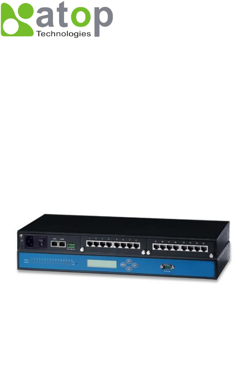
Atop Industrial Serial Device Server SE5408A/SE5416A Series User Manual V 1.0 3.3 Panel Layout and Dimensions Front and Rear Panels (SE5408A): Figure 3.1 Front and Rear Panels (SE5416A): Figure 3.
Atop Industrial Serial Device Server SE5408A/SE5416A Series User Manual V 1.0 3.4 First Time Installation Before installing the device, please adhere to all safety procedures described below, Atop will not be held liable for any damages to property or personal injuries resulting from the installation or overall use of the device. Do not attempt to manipulate the product in any way if unsure of the steps described here, in such cases please contact your dealer immediately. 1.
Atop Industrial Serial Device Server SE5408A/SE5416A Series User Manual V 1.0 3.5 User Interface Overview The SE5416A Series is designed as a device capable of transmitting data between Serial and Ethernet; its user interface is designed intuitively for ease of use to suit the customer needs. The web configuration appears as follows, Figure 3.3. The device can be configured using our Serial Manager utility also, for more information, refer to Serial Manager’s manual. Figure 3.
Atop Industrial Serial Device Server SE5408A/SE5416A Series User Manual V 1.0 3.6 Factory Default Settings Upon arrival, the device will be set as follows: Parameters LAN 1 LAN 2 Default Values IP Address 10.0.50.100 Gateway 10.0.0.254 Subnet Mask 255.255.0.0 IP Address 192.168.1.1 Gateway 192.168.1.254 Subnet Mask 255.255.255.
Atop Industrial Serial Device Server SE5408A/SE5416A Series User Manual V 1.0 4 LCM Configuration There is an LCM (Liquid Crustal Monitor) installed on the front panel of the device that can be used to display device information and perform basic configurations. The table below illustrates its buttons and corresponding functions. Buttons Function Open Main Menu or go back one level higher Scroll up Scroll down Confirm the selection.
Atop Industrial Serial Device Server SE5408A/SE5416A Series User Manual V 1.0 4.2.1 Overview 1st layer 2nd layer 3rd layer 4th layer 5th layer 1.Model name Display Model name 2.Kernel ver. Display kernel version 3. AP ver. Display AP version 1.Lan status 1.Overview Descriptions Display LAN1 status 4.Lan 1 Display MAC address of 2.MAC LAN1 1.Lan status Display LAN2 status 5.Lan 2 Display MAC address of 2.MAC LAN2 4.2.
Atop Industrial Serial Device Server SE5408A/SE5416A Series User Manual V 1.0 4.2.3 Serial Settings 1st layer 2nd layer 3rd layer 4th layer 5th layer Descriptions Select a COM Port to 1.Select port configure 1. 300 2. 600 3. 1200 4. 2400 5. 4800 6. 9600 1.Baud Rate 7. 19200 Display/Change baud rate 8. 38400 9. 57600 10. 115200 11. 230400 3.Serial set 12. 460800 2.Parameter 13. 921600 set 1. None 2. Odd 2.Parity 3. Even Display/Change Parity 4. Mark 5.Space 1. 5 bits 3.Data bits 2.
Atop Industrial Serial Device Server SE5408A/SE5416A Series User Manual V 1.0 1. None Display/Change Flow 5.Flow control 2. Xon/Xoff control mode 3. Hardware 1.Disable Disable UART Delimiter 1.Timer: Change UART delimiter to timer mode and set its time 1.Net to serial 2.Enable 2.Char: Change UART delimiter to character mode and set the character 6.Delimiter 1.Disable Disable UART Delimiter 1.Timer: Change UART delimiter to timer mode and set its time 2.Serial to net 2.Enable 2.
Atop Industrial Serial Device Server SE5408A/SE5416A Series User Manual V 1.0 Display/Change Local 2.Local port listening port Display/Change 3.Max maximum client connect connection (1~4) 1.Disable 4.IP Filter Display/Change IP Filter function and the IP 2.Enable address 1.No 5. Apply to all 2.Yes Destination IP 1 Display/Change 2.Dest port 1 Destination port 1 1.Disable 3.Destination 2 to all serial ports Display/Change 1.Dest IP 1 2.
Atop Industrial Serial Device Server SE5408A/SE5416A Series User Manual V 1.0 1.No b.Apply to all 2.Yes Apply Link mode Settings to all serial ports 4.2.4 Server State 1st layer 2nd layer 3rd layer 4th layer 5th layer 1.Web 1.Disable Disable Web console console 2.Enable Enable Web console 2.Telnet 1.Disable Disable Telnet console console 2.Enable Enable Telnet console Descriptions 1.Console Disable LCM console 1.No password protection 1.LCM console Enable and change the 2.
Atop Industrial Serial Device Server SE5408A/SE5416A Series User Manual V 1.0 5 Web Configuration 5.1 Administrator Login As soon as the device is connected on the LAN, the user can proceed to navigate through its configuration using Serial Manager© (utility that comes in the CD); as noted in Figure 5.1 below, important information such as the IP, MAC address, etc. is going to be displayed. Figure 5.
Atop Industrial Serial Device Server SE5408A/SE5416A Series User Manual V 1.0 5.2 Overview This section gives a general status information on Device, network, ERPS and STP. Figure 5.2 Device Information, displays system Kernel and AP versions. Figure 5.
Atop Industrial Serial Device Server SE5408A/SE5416A Series User Manual V 1.0 Networking Information, displays both ‘LAN1 and LAN 2’sinformation on the overview page. The information provided with networking settings. Note: If the device is in the bridge mode, Bridge information will be shown instead. Figure 5.4 ERPS Information, displays Ring and Port status. Figure 5.
Atop Industrial Serial Device Server SE5408A/SE5416A Series User Manual V 1.0 Spanning Tree Information, STP and STP Port Information display the current STP settings and status. Figure 5.
Atop Industrial Serial Device Server SE5408A/SE5416A Series User Manual V 1.0 Figure 5.7 5.3 Network Configuration Click on the “Network” link to open network settings. LAN / Bridge Settings, when the bridge function is enabled, LAN1 and LAN2 will use the same IP address for redundancy. Therefore, LAN1 Settings will become Bridge Settings and LAN2 Settings will be disabled. When the bridge function is disabled, you can LAN1 and LAN2 can be in different subnets.
Atop Industrial Serial Device Server SE5408A/SE5416A Series User Manual V 1.0 Figure 5.8 DNS Settings, Fill in DNS (Domain Name System) information in order to have an external DNS server resolve domain name into IP address. This is crucial if the NTP and SMTP services use domain names instead of IP addresses. A DNS server will be retrieved from the DHCP server automatically if DHCP is enabled. Figure 5.
Atop Industrial Serial Device Server SE5408A/SE5416A Series User Manual V 1.0 SNMP Settings, The SNMP function is disabled by default. To enable this function check on “Enable SNMP” option. Basic SNMP configurations such as Read/Write Community, SysName (System Name), SysLocation (System Location), and SysContact (System Contact) are supported. In addition, you can send SNMP Trap events to a SNMP Trap server by entering its IP address.
Atop Industrial Serial Device Server SE5408A/SE5416A Series User Manual V 1.0 Label Description ERPS Choose whether to enable ERPS or not. RAPSD VLAN Specifies the ring’s R-APS VLAN ID. VLAN ID ranges from 1 to 4094, every ring should have its own ID. PRL Owner Enable to set this device as the RPL Owner. RPL Port Select the RPL Port when the device is an Owner. WTR Timer Set the wait-to-restore (WTR) time of the ring in minutes, ranges from 0 to 12 minutes.
Atop Industrial Serial Device Server SE5408A/SE5416A Series User Manual V 1.0 by bridges/switches to every port, the bridges/switches will repeatedly rebroadcast the broadcast messages, and this can flood the network. STP creates a spanning tree and disables those redundant links that are on the same level of the tree, which leaves only a single active path between any two nodes. This function avoids flooding and increases network efficiency. RSTP (Rapid Spanning Tree Protocol) are also supported.
Atop Industrial Serial Device Server SE5408A/SE5416A Series User Manual V 1.0 Figure 5.
Atop Industrial Serial Device Server SE5408A/SE5416A Series User Manual V 1.0 5.4 Serial Click on the “Serial” link to open its submenu and COM1 settings. Figure 5.
Atop Industrial Serial Device Server SE5408A/SE5416A Series User Manual V 1.0 5.4.1 COM Configuration This section will only focus on the serial settings (Figure 5.15). Details on connectivity protocols and their settings (Figure 5.14) are given in Link Modes and Applications. Figure 5.
Atop Industrial Serial Device Server SE5408A/SE5416A Series User Manual V 1.0 Figure 5.15 Match these settings with your serial device: UART Mode, Select between RS-232, RS-422, and RS-485. Note that RS-485 refers to 2-Wire RS-485 and RS-422 is compatible with 4-Wire RS-485. Baud Rate, Select one of the baudrates from the dropdown box. Parity/Data Bits/Stop Bits, Configure them accordingly.
Atop Industrial Serial Device Server SE5408A/SE5416A Series User Manual V 1.0 5.4.2 COM Configuration: Advanced Settings Click on the “Advanced Settings” button to open the dialog (Figure 5.16). Figure 5.16 TCP TCP Timeout, Specify the value in “TCP Timeout” to force SE5416A Series actively close a TCP connection after some specific inactivity time (no packets). The default value for it is 3600 seconds. Disabling this option means SE5416A Series would never actively close an established connection.
Atop Industrial Serial Device Server SE5408A/SE5416A Series User Manual V 1.0 transmit the serial data in its buffer over the network. Interval timeout, SE5416A Series will transmit the serial data in its buffer when the specified time interval has reached and no more serial data comes in. The default value is calculated automatically based on the baud rate.
Atop Industrial Serial Device Server SE5408A/SE5416A Series User Manual V 1.0 and has no effect on the Transparent Mode. When TCP data is received (request) and passed to Serial side, the device will wait for the set time before transferring another TCP data if the Serial side did not receive any data (response). Serial Serial FIFO, By default, SE5416A Series has its FIFO function enabled to optimize its serial performance.
Atop Industrial Serial Device Server SE5408A/SE5416A Series User Manual V 1.0 5.5 Alert Settings Click on the “Alert” link to open its submenu and E-mail settings. Figure 5.17 5.5.1 Email Settings In case the device raises an alert and/or warning message, it will send an email to the administrator’s mailbox. Email Settings allows you to set up the device to be able to send an email. To set up the email sending, you need to put a “Sender” email address which will be the “From” on the email.
Atop Industrial Serial Device Server SE5408A/SE5416A Series User Manual V 1.0 Figure 5.19 Attention It is also important to setup Default Gateway and DNS Servers in the Network Settings properly, so your SE5416A Series can lookup DNS names and route the mails to the proper default gateway. 5.5.2 Alert Event Events could be triggered in different ways. Including Cold Star, Warm Start, Authentication Failure, IP Change, Password Change, and Link Down.
Atop Industrial Serial Device Server SE5408A/SE5416A Series User Manual V 1.0 5.6 System Configuration Click on the “System” link to open its submenu and this will lead you to the Link State. Figure 5.21 5.6.1 Link State Link State displays the information of each connection for all serial ports for debugging purposes. It also displays the byte count of each serial port’s Transmit (Tx) and Receive (Rx) data. Figure 5.
Atop Industrial Serial Device Server SE5408A/SE5416A Series User Manual V 1.0 5.6.2 Log Settings The Syslog function is turned on by default and cannot be turned off. It is used to log system events and report to an external Syslog server if necessary. Also, Transmitted data could be logged for recording or debugging purposes. The logs could be reported to an external Syslog server as well. Figure 5.
Atop Industrial Serial Device Server SE5408A/SE5416A Series User Manual V 1.0 Figure 5.24 COM Log Settings Log Data Contents, if enabled, the COM logging function will log the content (raw bytes) of data that is being transmitted and received. If disabled, COM logging function will only log data length to reduce system load. Note: SE5416A Series can store up to 1500 lines internally. A request or a response will consist of one line, data longer than 512 bytes will go into another line.
Atop Industrial Serial Device Server SE5408A/SE5416A Series User Manual V 1.0 5.6.3 System Log Display the current syslog stored in the device. Figure 5.25 Click on “Last Page” to go to the last page. Click on “Show All Event” to show all events in one page. Click on “Clear All Event” to clear the events stored in the device. 5.6.4 COM Log You can select from the COMx dropdown box to display logs from different COM ports.
Atop Industrial Serial Device Server SE5408A/SE5416A Series User Manual V 1.0 5.6.5 Time Settings Date and time can be set manually, or using Network Time Protocol (NTP) to automatically synchronizes with a Time Server. For auto-synching select NTP in the Time Setting field, proceeding then to fill the IP address or host name for it. If a hostname is entered, the DNS server must be configured properly; a Time Zone can be selected as well.
Atop Industrial Serial Device Server SE5408A/SE5416A Series User Manual V 1.0 Figure 5.27 5.6.6 Security Configuration Figure 5.28 Change Password Enter the old password in the “Old Password” field; enter the new password in the “New Password” and the “Verified Password” fields, and then click on “Save Configuration” to update the password. Note: You can press the reset button on the device to reset the password to its default value (blank), in case it is forgotten.
Atop Industrial Serial Device Server SE5408A/SE5416A Series User Manual V 1.0 the LCM to select the characters one by one. Reset Button Protect – Resetting the device back to the defaults becomes impossible when the reset button is protected. 5.6.7 Import/Export Once all the configurations are set and the device is working properly, you may want to back up your configuration.
Atop Industrial Serial Device Server SE5408A/SE5416A Series User Manual V 1.0 5.6.8 Set to Default Click on “Set to Default and Restart” button to restore the device’s settings to Factory Default Settings. Figure 5.31 5.6.9 Restart Click on the “Restart” button to restart the device. The web page will refresh after the device complete the reboot. Figure 5.
Atop Industrial Serial Device Server SE5408A/SE5416A Series User Manual V 1.0 6 CLI Configuration 6.1 Accessing the CLI SE5416A Series can be configured by CLI (Command-Line Interface). There are two ways to access the CLI. Both methods will lead to the same CLI, i.e., a command line interface that allows you to modify most settings in your device. 6.1.1 Serial Console The console interface follows standard RS-232 specification, find pin assignments in Section 9.3.2.
Atop Industrial Serial Device Server SE5408A/SE5416A Series User Manual V 1.0 Figure 6.1 6.2 General Information Open the command line interface (console terminal) and telnet to the device using its IP address. The default username is “admin” and password is empty (blank). A main menu should appear, Figure 6.2. Figure 6.2 Note: 1. SE5416A Series will automatically close the telnet connection after three minute of inactivity.
Atop Industrial Serial Device Server SE5408A/SE5416A Series User Manual V 1.0 2. Press the “ESC” key to return to the previous menu. 3. Some changes to the device would take effect only after the device is restarted. 4. Detailed explanations are embedded in the LCM Configuration There is an LCM (Liquid Crustal Monitor) installed on the front panel of the device that can be used to display device information and perform basic configurations.
Atop Industrial Serial Device Server SE5408A/SE5416A Series User Manual V 1.0 6.4.1 Overview 1st layer 2nd layer 3rd layer 4th layer 5th layer 1.Model name Display Model name 2.Kernel ver. Display kernel version 3. AP ver. Display AP version 1.Lan status 1.Overview Descriptions Display LAN1 status 4.Lan 1 Display MAC address of 2.MAC LAN1 1.Lan status Display LAN2 status 5.Lan 2 Display MAC address of 2.MAC LAN2 6.4.
Atop Industrial Serial Device Server SE5408A/SE5416A Series User Manual V 1.0 6.4.3 Serial Settings 1st layer 2nd layer 3rd layer 4th layer 5th layer Descriptions Select a COM Port to 1.Select port configure 1. 300 2. 600 3. 1200 4. 2400 5. 4800 6. 9600 1.Baud Rate 7. 19200 Display/Change baud rate 8. 38400 9. 57600 10. 115200 11. 230400 3.Serial set 12. 460800 2.Parameter 13. 921600 set 1. None 2. Odd 2.Parity 3. Even Display/Change Parity 4. Mark 5.Space 1. 5 bits 3.Data bits 2.
Atop Industrial Serial Device Server SE5408A/SE5416A Series User Manual V 1.0 1. None Display/Change Flow 5.Flow control 2. Xon/Xoff control mode 3. Hardware 1.Disable Disable UART Delimiter 1.Timer: Change UART delimiter to timer mode and set its time 1.Net to serial 2.Enable 2.Char: Change UART delimiter to character mode and set the character 6.Delimiter 1.Disable Disable UART Delimiter 1.Timer: Change UART delimiter to timer mode and set its time 2.Serial to net 2.Enable 2.
Atop Industrial Serial Device Server SE5408A/SE5416A Series User Manual V 1.0 Display/Change Local 2.Local port listening port Display/Change 3.Max maximum client connect connection (1~4) 1.Disable 4.IP Filter Display/Change IP Filter function and the IP 2.Enable address 1.No 5. Apply to all 2.Yes Destination IP 1 Display/Change 2.Dest port 1 Destination port 1 1.Disable 3.Destination 2 to all serial ports Display/Change 1.Dest IP 1 2.
Atop Industrial Serial Device Server SE5408A/SE5416A Series User Manual V 1.0 1.No b.Apply to all 2.Yes Apply Link mode Settings to all serial ports 6.4.4 Server State 1st layer 2nd layer 3rd layer 4th layer 5th layer Descriptions 1.Web 1.Disable Disable Web console console 2.Enable Enable Web console 2.Telnet 1.Disable Disable Telnet console console 2.Enable Enable Telnet console 1.Console Disable LCM console 1.No password protection 1.LCM console Enable and change the 2.
Atop Industrial Serial Device Server SE5408A/SE5416A Series User Manual V 1.0 This system overview window gives the general information on Ethernet, MAC address, kernel and AP version, ERPS, and STP status. Operation: Main → [1]Overview Figure 6.
Atop Industrial Serial Device Server SE5408A/SE5416A Series User Manual V 1.0 6.5 Networking Configuration This section allows you to change IP address, subnet mask, gateway, and SNMP information. Please note that the new settings will not take effect until the device is restarted. Operation: Main → [2]Networking Figure 6.4 6.5.1 LAN 1 / LAN 2 Settings Enter “LAN settings” and you will see a menu to configure the DHCP, IP address, subnet mask, and gateway of that LAN.
Atop Industrial Serial Device Server SE5408A/SE5416A Series User Manual V 1.0 Note: It is not possible to configure LAN1 or LAN2 when bridge mode is enabled. Please go to the Bridge Settings instead. 6.5.2 DNS Settings You can configure the DNS1 or DNS2 Server IP Address manually. Alternatively, if you enable the DHCP option in “LAN 1 Settings”, SE5416A Series will retrieve the DNS server address from the DHCP server automatically. Operation: Main → [2]Networking → [3]DNS Settings Figure 6.6 6.5.
Atop Industrial Serial Device Server SE5408A/SE5416A Series User Manual V 1.0 Figure 6.7 6.5.4 Bridge Settings SE5416A Series has a bridge mode that can be enabled. When the bridge mode is enabled, LAN1 and LAN2 would be merged to create one single Ethernet interfaces. When one of the physical LAN port fails, SE5416A Series would automatically use the other LAN port. Configure network settings of the bridge here. Operation: Main → [2]Networking → [6]Bridge Settings Figure 6.8 6.5.
Atop Industrial Serial Device Server SE5408A/SE5416A Series User Manual V 1.0 Figure 6.9 Note: It is not possible to enable ERPS when Bridge is disabled.
Atop Industrial Serial Device Server SE5408A/SE5416A Series User Manual V 1.0 6.5.6 STP Settings STP function in SE5416A Series can be enabled or disabled. Once enabled, you can set STP version, priority, maximum age, hello time, forward delay, port path cost, port priority, port P2P, and port Edge. Operation: Main → [2]Networking → [8]STP Settings Figure 6.10 Note: It is not possible to enable STP when Bridge is disabled.
Atop Industrial Serial Device Server SE5408A/SE5416A Series User Manual V 1.0 6.6 COM Port Configuration SE5416A Series allows you to configure the parameters of the COM port including COM Link mode and COM port parameters. First enter the number of the COM port that you want to configure. Figure 6.11 6.6.1 TCP Server for Link Mode TCP Server mode is the default Link Mode for SE5416A Series. A TCP Client is required to connect to this TCP Server.
Atop Industrial Serial Device Server SE5408A/SE5416A Series User Manual V 1.0 (if enabled). Operation: Main [6]COM Port Setting[1-4]Select Port[1]Link Mode[2]TCP Client Figure 6.13 6.6.3 UDP Link Mode SE5416A Series’ Link Mode can be configured to utilize UDP. Note that UDP is a connection-less protocol, so data delivery is not guaranteed. You will need to configure the settings of Destination IPs. The Destination IP field supports input of IP range and up to eight Destination IPs are supported.
Atop Industrial Serial Device Server SE5408A/SE5416A Series User Manual V 1.0 Operation: Main [6]COM Port Setting[1-4]Select Port[2]Com Settings Figure 6.15 6.7 Alert Settings There are two sub-menu settings included inside the Alert Settings, which are E-mail Settings and Alert Event. Figure 6.16 6.7.1 Configuring E-mail When an alert event triggered, SE5416A Series can send that event through email.
Atop Industrial Serial Device Server SE5408A/SE5416A Series User Manual V 1.0 Figure 6.17 6.7.2 Configuring Alert Event Choose the Alert events that SE5416A Series should trigger and the method it should use to notify that event (Email, Trap, or Relay). Available events are Cold Start, Warm Start, Authentication Failure, IP Address Change, Password Change, and Link Down. Operation: Main [7]Alert Settings[2]Alert Event Figure 6.
Atop Industrial Serial Device Server SE5408A/SE5416A Series User Manual V 1.0 6.8 System Configuration There are three sub-menus included inside the System Settings, which are Link State, Time, and Security. Operation: Main [8]System Figure 6.19 6.8.1 Link State Link State information of each COM port will be displayed.
Atop Industrial Serial Device Server SE5408A/SE5416A Series User Manual V 1.0 Figure 6.20 6.8.2 Time Settings You can configure the system time manually or let SE5416A Series retrieve time information from a NTP server. The changed will take effect immediately after the settings are saved. Operation: Main [8]System[2]Time Figure 6.21 6.8.3 Security Settings You can change the system password here. Moreover, you can block different access method to prevent system intrusion.
Atop Industrial Serial Device Server SE5408A/SE5416A Series User Manual V 1.0 6.9 Restoring Factory Default Choose and confirm this option to reset SE5416A Series back to its default settings. The device would restart automatically to apply the default settings. Operation: Main [9]Set to Default Figure 6.23 6.10 Restart System Choose and confirm this option to restart SE5416A Series. Operation: main → [a]Restart Figure 6.
Atop Industrial Serial Device Server SE5408A/SE5416A Series User Manual V 1.0 7 Link Modes and Applications 7.1 Link Mode Configuration SE5416A Series supports different Link Modes, which are TCP Server, TCP Client, and UDP. Under the three Link Modes, TCP Server can support RAW, Virtual COM, or Reverse Telnet applications. TCP Client can support Virtual COM application. In the upcoming sections, we will discuss how to setup different Link Modes properly.
Atop Industrial Serial Device Server SE5408A/SE5416A Series User Manual V 1.0 7.1.1 TCP Server Mode SE5416A Series can be configured as a TCP server in a TCP/IP Network to listen for an incoming TCP client connection to a serial device. After the connection is established between the serial device server and the host computer, data can be transmitted in both directions; this also applies whenever the VCOM is running on server mode. Please be reminded that this is the device’s default link mode. Figure 7.
Atop Industrial Serial Device Server SE5408A/SE5416A Series User Manual V 1.0 Figure 7.2 For setting as a TCP Server, please follow these steps. Click on the COMX link under Serial on the left hand side. Select TCP Server in the Link Modes; TCP Server is the default link mode. Also in this section you will find the following options. Mode, there are 3 different communication modes here: RAW, there is no protocol on this mode, meaning the data is passed transparently.
Atop Industrial Serial Device Server SE5408A/SE5416A Series User Manual V 1.0 Sec. 5.4.1. For Advanced settings, go to Sec. 5.4.2. Scroll to the bottom of the page and click on “Save Configuration” button to save the changes. Other important variables to consider are: IP Filter, enables the Source IP option below to block an IP address from accessing the COM port. Source IP, specifies the device’s Source IP which will be transmitting data to our Server.
Atop Industrial Serial Device Server SE5408A/SE5416A Series User Manual V 1.0 7.1.2 TCP Client Mode SE5416A Series can be configured as a TCP client in TCP/IP Network to establish a connection with a TCP server in the host computer. After the connection is established, data can be transmitted between a serial device and a host computer in both directions; this also applies to Virtual COM running in the client mode. Figure 7.
Atop Industrial Serial Device Server SE5408A/SE5416A Series User Manual V 1.0 Figure 7.4 For setting as a TCP Client, please follow these steps. Click on the COMX port under Serial on the left hand side. Select TCP Client in the Link modes. Only two communication modes are available here: RAW and Virtual COM which definitions are the same as above in Mode. Enter the preferred Destination IP and Port. This should match the IP settings of the TCP Server program.
Atop Industrial Serial Device Server SE5408A/SE5416A Series User Manual V 1.0 7.1.3 UDP Mode UDP is a faster but connectionless network protocol; it does not guarantee the delivery of network datagram. The SE5416A Series can be configured to transfer data using unicast or multicast UDP from the serial device to one or multiple host computers, data can be transmitted between serial device and host computer in both directions.
Atop Industrial Serial Device Server SE5408A/SE5416A Series User Manual V 1.0 Figure 7.6 Click on the COMX port under Serial on the left hand side. Select UDP in the Link modes. Destination IP and Port: Specify the Begin and End IP here. Four groups of range IPs are allowed. This is the IP address of the UDP program and the Port it is listening to. Note that the maximum number of UDP nodes that SE5416A Series can handle would highly depend on the traffic load.
Atop Industrial Serial Device Server SE5408A/SE5416A Series User Manual V 1.0 7.2 Link Mode Applications 7.2.1 TCP Server Application: Enable Virtual COM SE5416A Series will encapsulate control packets on top of the real data when Virtual COM is enabled. This will allow the Virtual COM port in the Windows/Linux system to access SE5416A Series’ COM ports. The benefit of using Virtual COM is that rewriting an existing COM program to read IP packets is unnecessary.
Atop Industrial Serial Device Server SE5408A/SE5416A Series User Manual V 1.0 Serial/IP Virtual COM’s Control Panel later. 7.2.2 TCP Server Application: Enable RFC 2217 The underlying protocol of Virtual COM is based on RFC 2217, the Telnet COM Control Option. Therefore, it is possible to use RFC 2217 with SE5416A Series in the TCP Server mode. To do so, refer to Sec 7.2.1 to enable Virtual COM, so that SE5416A Series becomes aware of the commands.
Atop Industrial Serial Device Server SE5408A/SE5416A Series User Manual V 1.0 Virtual COM application in SE5416A Series. Scroll to the bottom of the page and click on “Save Configuration” button to save the changes. Configure Virtual COM in the Operating System. For Windows, refer to Chapter 8. For Linux, refer to a separate manual included in the Linux driver zip file. Remember the Destination Port here in order to enter this information in Serial/IP Virtual COM’s Control Panel later. 7.2.
Atop Industrial Serial Device Server SE5408A/SE5416A Series User Manual V 1.0 Figure 7.9 Follow Sec. 7.2.1 to configure SE5416A Series in TCP Server mode properly. Click on the dropdown box of the Mode option and switch to “Virtual COM” to enabled Virtual COM application in SE5416A Series. Scroll to the bottom of the page and click on “Save Configuration” button to save the changes. Remember Pair Connection Master’s IP address here in order to enter this information in the Slave later.
Atop Industrial Serial Device Server SE5408A/SE5416A Series User Manual V 1.0 Figure 7.10 Follow Sec. 7.1.2 to configure SE5416A Series in TCP Client mode properly. Click on the dropdown box of the Mode option and switch to “Virtual COM” to enabled Virtual COM application in SE5416A Series. Match the Destination IP with the settings of Pair Connection Master’s IP that was setup previously. Scroll to the bottom of the page and click on “Save Configuration” button to save the changes. 7.2.
Atop Industrial Serial Device Server SE5408A/SE5416A Series User Manual V 1.0 Figure 7.11 Follow Sec. 7.2.1 to configure SE5416A Series in TCP Server mode properly. Click on the dropdown box of the Mode option and switch to “Reverse Telnet” to enabled Reverse Telnet application in SE5416A Series. Scroll to the bottom of the page and click on “Save Configuration” button to save the changes. 7.2.
Atop Industrial Serial Device Server SE5408A/SE5416A Series User Manual V 1.0 IP Address Link Mode Local Listening Port Destination IP Destination Port SE5416A Master COM1 10.0.50.100 UDP 5000 10.0.50.200~10.0.50.202 5000 SE5416A Master COM1 10.0.50.100 UDP 5001 10.0.50.200~10.0.50.201 5000 SE5416A Master COM1 10.0.50.100 UDP 5002 10.0.50.200 5000 SE5416A Slave 1 COM1 10.0.50.200 UDP 5000 10.0.50.100 5000 SE5416A Slave 1 COM2 10.0.50.200 UDP 5001 10.0.50.
Atop Industrial Serial Device Server SE5408A/SE5416A Series User Manual V 1.0 7.2.9 TCP Server Application: Multiple TCP Connections The Multi-Connection option will allow up to a maximum of four TCP Client connections. Note that it is also possible to use this multi-connection feature in conjunction with other TCP Server applications, such as Virtual COM, Pair Connection, and Reverse Telnet.
Atop Industrial Serial Device Server SE5408A/SE5416A Series User Manual V 1.0 7.2.10 TCP Server Application: Multi-Point TCP Pair Connections The difference between Multi-Point TCP Pair Connection and Multi-Point UDP Pair Connection is that the TCP implementation would also exchange flow control pins for RS-232. However, the TCP Server is limited to a maximum of four connections.
Atop Industrial Serial Device Server SE5408A/SE5416A Series User Manual V 1.0 8 VCOM Installation & Troubleshooting 8.1 Enabling VCOM SE5416A Series will encapsulate control packets on top of the real data when Virtual COM is enabled. This will allow the Virtual COM port in the Windows/Linux system to access SE5416A Series’ COM ports. Remember that VCOM can only be enabled on TCP Server Mode or TCP Client, Figure 8.1. Figure 8.
Atop Industrial Serial Device Server SE5408A/SE5416A Series User Manual V 1.0 Figure 8.2 Virtual COM allows remote access of serial devices over TCP/IP networks through Serial/IP Virtual COM ports that work like local native COM ports; Figure 8.3 is a Virtual COM connection diagram.
Atop Industrial Serial Device Server SE5408A/SE5416A Series User Manual V 1.0 Figure 8.3 8.1.1 VCOM driver setup System Requirements Windows 7/2008/Vista/2003/XP/2000/NT4/9x (32-bit or 64-bit version automatically installs) Native and virtual platforms, including Virtual Server and VMware Linux, also available but first you might need to download a separate package called Virtual COM driver for Linux (TTYredirector) available for download on Atop website or in the product CD.
Atop Industrial Serial Device Server SE5408A/SE5416A Series User Manual V 1.0 8.1.3 Installation Run the Virtual COM setup file included in the CD or download a copy from our website to install the Virtual COM driver for the operating system. Turn off your anti-virus software and try again if installation fails. At the end of the installation, please select at least one Virtual COM port from the Serial/IP Control Panel. 8.1.
Atop Industrial Serial Device Server SE5408A/SE5416A Series User Manual V 1.0 8.2.2 Running Serial/IP in Windows Find Serial/IP Control Panel from: Start → All Programs → Serial/IP → Control Panel In the Windows Control Panel, open the Serial/IP applet. In the Windows notification area, Figure 8.5; right click in the Serial/IP tray icon and click on Configure to open the Control Panel. Figure 8.
Atop Industrial Serial Device Server SE5408A/SE5416A Series User Manual V 1.0 Figure 8.6 After at least one Virtual COM port is selected, the Control Panel will show, Figure 8.7.
Atop Industrial Serial Device Server SE5408A/SE5416A Series User Manual V 1.0 Figure 8.7 The left hand side of the Control Panel shows the list of selected Virtual COM ports. Click on Select Ports to add or remove Virtual COM ports from the list. The right hand side of the Control Panel shows the configurations of the selected Virtual COM port marked in blue. Each Virtual COM port can have its own settings.
Atop Industrial Serial Device Server SE5408A/SE5416A Series User Manual V 1.0 8.2.3 Configuring VCOM Ports If the serial device server is running in TCP Server mode (recommended), a Serial/IP should be the TCP Client connecting to the serial device server. Enable Connect to Server and enter the IP Address of the serial device server with the Port Number specified. The Port Number here is the Local Listening Port for the serial device server.
Atop Industrial Serial Device Server SE5408A/SE5416A Series User Manual V 1.0 click on Use Settings. Click on Copy to copy the results to the system clipboard. To transfer the settings between Virtual COM ports, click on the Copy Settings To button. Figure 8.9 8.2.
Atop Industrial Serial Device Server SE5408A/SE5416A Series User Manual V 1.0 Figure 8.10 If the exclamation mark begins with Warning: timeout trying x.x.x.x as in Figure 8.10, recheck the VCOM IP and Port configuration or the PC’s network configuration.
Atop Industrial Serial Device Server SE5408A/SE5416A Series User Manual V 1.0 Figure 8.11 If there is a check with Raw Connection Detected and an exclamation mark with Client not licensed for this server, Figure 8.11, enable VCOM in the serial device server.
Atop Industrial Serial Device Server SE5408A/SE5416A Series User Manual V 1.0 Figure 8.12 If there is a check with Telnet Protocol Detected and an exclamation mark with Client not licensed for this server as in Figure 8.12, this means that there is a licensing issue between the serial device server and Serial/IP. Please contact Atop technical support to obtain the correct VCOM software.
Atop Industrial Serial Device Server SE5408A/SE5416A Series User Manual V 1.0 Figure 8.13 If the exclamation mark begins with Server requires username/password login Figure 8.13 It means VCOM Authentication in the serial device server is enabled, but credentials in the Serial/IP are not enabled.
Atop Industrial Serial Device Server SE5408A/SE5416A Series User Manual V 1.0 Figure 8.14 If the exclamation mark begins with a “Username and/or password incorrect”, Figure 8.14; this means the wrong username and/or password were entered and the authentication process failed.
Atop Industrial Serial Device Server SE5408A/SE5416A Series User Manual V 1.0 Figure 8.15 If the exclamation mark begins with No login/password prompts received from server Figure 8.15, it means credentials in the Serial/IP is enabled, but VCOM Authentication in the serial device server is not enabled.
Atop Industrial Serial Device Server SE5408A/SE5416A Series User Manual V 1.0 8.3 Using Serial/IP Port Monitor 8.3.1 Opening the Port Monitor The Serial/IP Port Monitor can be opened by: Start → All Programs → Serial/IP → Port Monitor Double click the Serial/IP tray icon in the Windows notification area. In the Windows notification area, right click in the Serial/IP tray icon and click on Port Monitor to open the Port Monitor.
Atop Industrial Serial Device Server SE5408A/SE5416A Series User Manual V 1.0 8.3.3 The Trace Panel Figure 8.17 The Trace panel provides a detailed, time-stamped, real-time display of all Serial/IP COM ports operations, Figure 8.17. Click on Enable Trace to start logging Virtual COM communication. Click on File → Save As and send the log to Atop for analysis if problems arise with Virtual COM. 8.3.
Atop Industrial Serial Device Server SE5408A/SE5416A Series User Manual V 1.0 Figure 8.
Atop Industrial Serial Device Server SE5408A/SE5416A Series User Manual V 1.0 keep-alive message, if no there is no activity Maximum Connection Recovery Interval Controls the maximum time for “Restore Failed Connection” Enable SETXON/SETXOFF COM Port Commands This option enables additional negotiation on SETXON and SETXOFF commands and is only available for the “V” series serial device servers. If the application requires SETXON/SETXOFF feature, please contact Atop Tech Support. 8.3.
Atop Industrial Serial Device Server SE5408A/SE5416A Series User Manual V 1.0 9 Specifications 9.1 Hardware Network Interface Ethernet 2x RJ’45 IEEE802.
Atop Industrial Serial Device Server SE5408A/SE5416A Series User Manual V 1.0 9.2 Software Protocols DHCP Client, DNS, ERPS, HTTP, ICMP, IPv4, NTP, RFC2217, SMTP, SNMP, STP, Syslog, TCP, Telnet, UDP Configuration Serial Manager, Web UI, Serial console, Telnet Virtual COM Windows / Linux redirection software Link Modes TCP Server 4 connections, Virtual COM, or Reverse Telnet TCP Client Dual destinations or Virtual COM UDP Up to 8 ranges of IPs 9.3 Pin Assignments 9.3.
Atop Industrial Serial Device Server SE5408A/SE5416A Series User Manual V 1.0 9.3.2 Serial and Female DB9 Connectors RS-232 RS-485 RS-422 Pin 1 - - - Pin 2 RXD Data+ RX+ Pin 3 TXD - TX+ Pin 4 DTR - TX- Pin 5 SG SG SG Pin 6 DSR Data- RX- Pin 7 RTS - - Pin 8 CTS - - Pin 9 - - - 9.3.
Atop Industrial Serial Device Server SE5408A/SE5416A Series User Manual V 1.0 9.3.4 RJ-45 to Female DB9 Connection RJ45 Cross Over Female DB9 RTS Pin 1 Pin 8 CTS DTR Pin 2 Pin 6 DSR TXD Pin 3 Pin 2 RXD SG Pin 4 GND Pin 5 Pin 5 SG RXD Pin 6 Pin 3 TXD DSR Pin 7 Pin 4 DTR CTS Pin 8 Pin 7 RTS 9.3.
Atop Industrial Serial Device Server SE5408A/SE5416A Series User Manual V 1.0 9.
Atop Industrial Serial Device Server SE5408A/SE5416A Series User Manual V 1.0 10 Upgrade System Firmware 10.1 Upgrade Procedure Obtain new firmware from http://www.atop.com.tw Make sure the PC and the SE5416A Series are on the same network; use the ping command or Serial Manager© utility for it. Edit “dll.bat” to fit the system requirements, be sure to save your settings before. Run linux_dl, for example: linux_dl_v2_zImage.bin 10.0.50.
Atop Industrial Serial Device Server SE5408A/SE5416A Series User Manual V 1.0 11 Warranty Limited Warranty Conditions Products supplied by us are covered in this warranty for undesired performance or defects resulting from shipping, or any other event deemed to be the result of Atop Technologies’ mishandling.