SW550xC Industrial Wireless Serial Device Server Series User’s Manual v. 1.
Industrial Wireless Serial Device Server Series SW550xC User Manual V 1.0 Important Announcement The information contained in this document is the sole property of Atop Technologies, Inc. and is supplied for the sole purpose of operation and maintenance of Atop Technologies, Inc. products.
Industrial Wireless Serial Device Server Series SW550xC User Manual V 1.0 Contents 1 Preface ..................................................................................................... 1 2 Introduction.............................................................................................. 4 3 4 2.1 Product Overview ......................................................................................................4 2.2 Features ....................................................
Industrial Wireless Serial Device Server Series SW550xC User Manual V 1.0 4.9.2 COM Log Settings .......................................................................................... 42 4.9.3 Event Log ....................................................................................................... 43 4.9.4 COM Datalog ................................................................................................. 44 4.10 System Setup........................................................
Industrial Wireless Serial Device Server Series SW550xC User Manual V 1.0 6 VCOM Installation & Troubleshooting ................................................. 88 6.1 6.2 Enabling VCOM ...................................................................................................... 88 6.1.1 VCOM driver setup ........................................................................................ 90 6.1.2 Limitation ...............................................................................
1 Preface Purpose of the Manual This manual supports you during the installation and configuring of the SW550xC Series only, as well as it explains some technical options available with the mentioned product. As such, it contains some advanced network management knowledge, instructions, examples, guidelines and general theories designed to help users manage this device and its corresponding software; a background in general theory is a must when reading it.
Industrial Wireless Serial Device Server Series SW550xC User Manual V 1.0 1 This device may not cause harmful interference, and 2 This device must accept any interference received, including interference that may cause undesired operation. This device and its antenna(s) must not be co-located or operating in conjunction with any other antenna or transmitter.
Industrial Wireless Serial Device Server Series SW550xC User Manual V 1.0 European Union This system has been evaluated for RF exposure for Humans in reference to the ICNIRP (International Commission on Non-Ionizing Radiation Protection) limits.
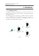
Industrial Wireless Serial Device Server Series SW550xC User Manual V 1.0 2 Introduction 2.1 Product Overview The SW550xC Industrial Wireless Serial Device Server is the newest in our wireless series designed to provide connectivity to clients and serial devices creating a complete solution for your wireless networking.
Industrial Wireless Serial Device Server Series SW550xC User Manual V 1.0 2.2 Features The SW550xC Series is our latest addition to our Industrial Wireless products; its small size but powerful architecture makes it a perfect choice for industrial/manufacturing needs in which size is a decisive factor. It rewards our customers with superb connectivity withstanding all the harshness in your environment of choice. Among its many characteristics, we could mention: 2.4 GHz with other wireless devices.
Industrial Wireless Serial Device Server Series SW550xC User Manual V 1.0 3 Getting Started 3.1 Inside the Package Inside the product purchased you will find the following items: Table 3.1 SW5501C Item Qty Description SW5501C 1 Industrial Wireless Serial Device Server Antenna 1 3~5 dBi antenna DB9 1 9-pin plug of the D-Sub connector family TB5 1 5-pin 5.
Industrial Wireless Serial Device Server Series SW550xC User Manual V 1.0 Table 3.3 SW5502C-TB Item Qty Description SW5502C-TB 1 Industrial Wireless Serial Device Server Antenna 1 3~5 dBi antenna TB5 2 5-pin 5.
Industrial Wireless Serial Device Server Series SW550xC User Manual V 1.0 3.2 Front & Power Panels The Front, and Power panels, are as follow: Figure 3.1 Figure 3.2 Figure 3.3 Figure 3.4 NOTE: the following front panel figures correspond to the following models.
Industrial Wireless Serial Device Server Series SW550xC User Manual V 1.0 Model Figure SW5501C Figure 3.1Figure 3.2 SW5502C Figure 3.2 SW5502C-TB Figure 3.3 The Rear panel (where you can mount the device on a rail or to the wall), looks as in Figure 3.5, a simple mounting instruction is given on Figure 3.6. Figure 3.5 Figure 3.
Industrial Wireless Serial Device Server Series SW550xC User Manual V 1.0 3.3 Serial Pin Assignments 3.3.1 DB9 Table 3.
Industrial Wireless Serial Device Server Series SW550xC User Manual V 1.0 3.3.2 Terminal Block Table 3.5 RS-232 4-W RS-422/RS-485 2-W RS-485 Full Duplex Half Duplex Half Duplex Pin# 1 SG SG SG 2 RTS R- DATA- 3 TxD R+ DATA+ 4 CTS T- N/A 5 RxD T+ N/A 3.
Industrial Wireless Serial Device Server Series SW550xC User Manual V 1.0 3.5 User Interface Overview The SW550xC Series is designed as a Wireless Client with the ability to choose between two different WLAN and LAN networks, its user interface is designed intuitively for ease of use to suit the customer needs. The web configuration appears as follows, Figure 3.7. Figure 3.7 On the left side, a menu-tree appears with all the modes and options available (Figure 3.
Industrial Wireless Serial Device Server Series SW550xC User Manual V 1.0 It is also worth noting that as a first step to view your device’s overall settings, you should use Serial Manager© (the utility provided in the CD). There will be however, three buttons which will be present during almost each section, Table 3.6. Table 3.6 Button Function Saves and apply the current configuration input on the page. As the caption implies, it applies the current configuration until the device is restarted.
Industrial Wireless Serial Device Server Series SW550xC User Manual V 1.0 Other relevant default settings are as in Table 3.8. Table 3.
Industrial Wireless Serial Device Server Series SW550xC User Manual V 1.0 4 Configuration 4.1 Administrator Login As soon as the device is connected on the web, the user can proceed to navigate through its configuration using Serial Manager© , (utility that comes in the CD); as noted in Figure 4.1 ,below, important information such as the IP, MAC address, etc is going to be displayed. Figure 4.
Industrial Wireless Serial Device Server Series SW550xC User Manual V 1.0 4.2 Operation Mode This is the welcome screen for the SW550xC Series. There are two operation modes to choose from: Wireless Client and AP Client. In Wireless Client mode, SW550xC will have two independent network interfaces, LAN and WLAN. Each interface would have its own IP address; hence traffics from the LAN interface would not be bypassed to the WLAN interface, and vice versa.
Industrial Wireless Serial Device Server Series SW550xC User Manual V 1.0 4.3 Overview Here you will find overall as well as general information. Figure 4.
Industrial Wireless Serial Device Server Series SW550xC User Manual V 1.0 Figure 4.
Industrial Wireless Serial Device Server Series SW550xC User Manual V 1.0 4.3.1 Wireless Status Wireless Network values will be displayed in this section, the default and current information can be compared side by side. Please remember to always keep a copy of your own preferred settings. Figure 4.
Industrial Wireless Serial Device Server Series SW550xC User Manual V 1.0 4.3.2 Site Monitor Site Monitor allows users to view other wireless networks in the neighborhood, it also provides information on other access points such as SSID, Channel used, the RSSI (Received Signal Strength Indicator), Security and other parameters used by other access points.
Industrial Wireless Serial Device Server Series SW550xC User Manual V 1.0 Figure 4.
Industrial Wireless Serial Device Server Series SW550xC User Manual V 1.0 4.4 Network Settings The SW550xC series has the ability for dual connections, i.e., WLAN and LAN at the same time. It can also get IP information automatically from a DHCP server as well, just check “Obtain an IP Address Automatically” for it; or enter the values manually if known. Gratuitous ARP – Enable to periodically send out an ARP response automatically to announce that SW550xC is in the network.
Industrial Wireless Serial Device Server Series SW550xC User Manual V 1.0 Default Gateway Selection specifies whether you are intending to use wireless or LAN interface as the default gateway. The selected interface is usually the one that is connected to a gateway or Internet. Settings from one of them will not be applicable to the other, i.e., if the WLAN is selected over the LAN then IP, Subnet mask, etc., on the LAN side will be OFF.
Industrial Wireless Serial Device Server Series SW550xC User Manual V 1.0 4.5 Wireless 4.5.1 Profiles You are allowed to save up to ten wireless profiles inside SW550xC. SW550xC will retry each and every enabled profile for one minute before continuing to the next profile if the current profile failed to connect. Use the Sort column to adjust the precedence of the profiles. This function is disabled by default. Figure 4.
Industrial Wireless Serial Device Server Series SW550xC User Manual V 1.0 4.5.2 Basic Settings To set up a wireless network, several parameters are needed as shown in Figure 4.12 (Wireless Profiles enabled) and Figure 4.13 (Wireless Profiles disabled).
Industrial Wireless Serial Device Server Series SW550xC User Manual V 1.0 Figure 4.
Industrial Wireless Serial Device Server Series SW550xC User Manual V 1.0 Figure 4.13 Attention We recommend using LAN interface to setup Wireless Configurations to avoid disconnection issues. The Web UI might freeze or lock up if the setup is made using the wireless interface because the connection would be lost whenever wireless settings are changed. It might take some time for the device to attach to the Access Point with new settings.
Industrial Wireless Serial Device Server Series SW550xC User Manual V 1.0 Default Settings in Infrastructure Mode: Table 3. 1 Caption Default SSID Null BSSID (MAC Address) Any (unless enabled) Topology Infrastructure Band Mode Automatic Detection 1 Bandwidth Automatic Detection Channel Automatic Detection Authentication Mode OPEN Encryption Type NONE Default Settings in Ad-Hoc Mode: Table 3.
Industrial Wireless Serial Device Server Series SW550xC User Manual V 1.0 possible to look for available wireless networks to attach to. Once clicked, it will start scanning and prompt a window. BSSID: this refers to the Access Point MAC address on which the SW550xC should connect to. Enabling this option will lock SW550xC to that Access Point, so SW550xC would not roam to another Access Point with the same SSID.
Industrial Wireless Serial Device Server Series SW550xC User Manual V 1.0 limited to 54Mbps. WEP Key: Enable when Authentication is set to OPEN and Encryption is set to WEP. Up to 4 different hexadecimal or ASCII keys can be entered in this section. WPA-PSK/WPA2-PSK Passphrase: Enable when Authentication is set to WPA-PSK or WPA2-PSK. It can be between 8 and 63 characters long. WPA2 (with RADIUS): Depending on the Authentication Mode selected, different fields would be enabled.
Industrial Wireless Serial Device Server Series SW550xC User Manual V 1.0 Figure 4.
Industrial Wireless Serial Device Server Series SW550xC User Manual V 1.0 4.5.3 Advanced Settings Provides details on wireless network parameters for performance tuning. Changes in this section may affect overall performance, so caution is recommended, if you are not clear of what you are doing please refrain from altering them, Figure 4.16. Figure 4.16 Radio Off – When enabled, this allows the user to turn off the wireless completely.
Industrial Wireless Serial Device Server Series SW550xC User Manual V 1.0 4.6 Serial 4.6.1 COM Port Overview Detail on connectivity protocols and its settings are given in Link Modes and Applications; this section will only focus on the serial settings. Figure 4.
Industrial Wireless Serial Device Server Series SW550xC User Manual V 1.0 4.6.2 COM Configuration Figure 4.18 Configure serial settings in this page, Figure 4.18. Note that these settings need to match the ones in the serial device. Serial Interface: Select between RS-232, RS-422, and RS-485. Note that RS-485 refers to 2-Wire RS-485 and RS-422 is compatible with 4-Wire RS-485. Baud Rate: Select one of the baudrates from the dropdown box. Parity / Data Bits / Stop Bits: Configure them accordingly.
Industrial Wireless Serial Device Server Series SW550xC User Manual V 1.0 4.6.3 COM Configuration: Advanced Settings Figure 4.19 TCP TCP Timeout: Specify the value in “TCP Timeout” to force SW550xC actively close a TCP connection after some specific inactivity time (no packets). The default value for it is 3600 seconds. Disabling this option means SW550xC would never actively close an established connection.
Industrial Wireless Serial Device Server Series SW550xC User Manual V 1.0 Interval timeout: SW550xC will transmit the serial data in its buffer when the specified time interval has reached and no more serial data comes in. The default value is calculated automatically based on the baud rate. If the automatic value results in chopped data, the timeout could be increased manually by switching to “Manual setting” and specifying a larger value.
Industrial Wireless Serial Device Server Series SW550xC User Manual V 1.0 data if the Serial side did not receive any data (response). Serial Serial FIFO: By default, SW550xC has its FIFO function enabled to optimize its serial performance.
Industrial Wireless Serial Device Server Series SW550xC User Manual V 1.0 4.7 SNMP/ALERT Settings The SNMP is used by network management software to monitor devices in a network to retrieve network status information and to configure network parameters. The SNMP Settings shows the configuration of this device so it can be viewed by third-party SNMP software as shown below, Figure 4.20. Figure 4.
Industrial Wireless Serial Device Server Series SW550xC User Manual V 1.0 If you wish to make the device information available for public viewing/editing, Enable the SNMP function. Fill in the passphrase for the “Read Community”, the group that is allowed to read the device information and fill in the passphrase for the “Write Community”, the group that is allowed to read/modify the device information. By default SW550xC comes in public for Read Community and private for Write Community.
Industrial Wireless Serial Device Server Series SW550xC User Manual V 1.0 4.8 E-mail Settings In case the device raises an alert and/or warning message, it will send an email to the administrator’s mailbox. Email Settings allows you to set up the device to be able to send an email. To set up the email sending, you need to put a “Sender” email address which will be the “From” on the email. Then, you fill in “Receiver” email address to which the email is sent.
Industrial Wireless Serial Device Server Series SW550xC User Manual V 1.0 4.9 Log Settings 4.9.1 System Log Settings The Syslog function is turned on by default and cannot be turned off. It is used to log system events and report to an external Syslog server if necessary. Figure 4.22 Enable Log Event to Flash: this would write log events to the local flash, otherwise the logs would be cleared when the device restarts because they are stored in the RAM by default.
Industrial Wireless Serial Device Server Series SW550xC User Manual V 1.0 4.9.2 COM Log Settings Transmitted data could be logged for recording or debugging purposes. The logs could be reported to an external Syslog server as well. Figure 4.23 Log Data Contents: if enabled, the COM logging function will log the content’s data that is being transmitted and received (raw bytes). If disabled, COM logging function will only log data length to reduce system load.
Industrial Wireless Serial Device Server Series SW550xC User Manual V 1.0 4.9.3 Event Log Display the current event log stored in the device. Figure 4.24 Click on “Last Page” to go to the last page. Click on “Show All Events” to show all events in one page. Click on “Clear All Events” to clear the events stored in the device. Click on “Save To File” to save all the events to a file locally.
Industrial Wireless Serial Device Server Series SW550xC User Manual V 1.0 4.9.4 COM Datalog Display the current COM log stored in the device. Figure 4.25 You can select from the COMx dropdown box to display logs from different COM ports. The first three lines were set to log data length and the last four lines were set to log data content. Click on “Last Page” to go to the last page. Click on “Show All Events” to show all events in one page.
Industrial Wireless Serial Device Server Series SW550xC User Manual V 1.0 4.10 System Setup 4.10.1 Date/Time Settings Date and time can be set manually, or using Network Time Protocol (NTP) to automatically synchronizes with a Time Server. For auto-synching check the box below NTP Server Settings “Obtain date/time automatically” proceeding then to fill the IP address or host name for it. If a hostname is entered, the DNS server must be configured properly; a Time Zone can be selected as well, Figure 4.
Industrial Wireless Serial Device Server Series SW550xC User Manual V 1.0 4.10.2 Admin Settings The SW550xC Series allows User and password management, the user’s default is as “admin” and the password will be in blank as default; to set/change their value just follow the steps filling in the corresponding blanks and choose Save & Apply in the end, Figure 4.27. Figure 4.27 There are two ways to access SW550xC’s Web UI.
Industrial Wireless Serial Device Server Series SW550xC User Manual V 1.0 4.10.3 Firmware Upgrade Updated firmware is provided by our company from time to time (for more information visit our News & Events webpage), to fix bugs and optimize performance. It is very important that the device must NOT be turned off or powered off during the firmware upgrading, (please be patient as this whole process might take up to 7 minutes).
Industrial Wireless Serial Device Server Series SW550xC User Manual V 1.0 4.10.4 Backup/Restore Setting Once all the configurations are set and the device is working properly, you may want to back up your configuration. Backup can be used when the new firmware is uploaded and it is reset to a factory default settings, it is done to prevent accidental loading of incompatible old settings.
Industrial Wireless Serial Device Server Series SW550xC User Manual V 1.0 4.10.5 Management List The Management List is used to filter the MAC address that has access to the Web management interface. When enabled, only the MAC addresses entered in the Access Control List below has access to the Web UI. Figure 4.
Industrial Wireless Serial Device Server Series SW550xC User Manual V 1.0 4.10.6 Ping Use the Ping function to determine whether SW550xC can reach the gateway or other devices in the network or not. This process takes around 20 seconds. Figure 4.31 represents a successful ping while Figure 4.32 means that the connecting device is not reachable. Figure 4.31 Figure 4.
Industrial Wireless Serial Device Server Series SW550xC User Manual V 1.0 4.11 Reboot and Restore Default Settings To manually reboot the device, you may click “Reboot”, after the click the device will restart. If a factory default setting is needed, the “Reset” checking box can be chosen, and then click on Reboot, Figure 4.33. Figure 4.
Industrial Wireless Serial Device Server Series SW550xC User Manual V 1.0 5 Link Modes and Applications 5.1 Link Mode Configuration SW550xC Series supports different Link Modes, which are TCP Server, TCP Client, and UDP. Under the three Link Modes, TCP Server can support RAW, Virtual COM, or Reverse Telnet applications. TCP Client can support Virtual COM application. In the upcoming sections, we will discuss how to setup different Link Modes properly. Figure 5.
Industrial Wireless Serial Device Server Series SW550xC User Manual V 1.0 5.1.1 Link Mode: Configure SW550xC as a TCP Server SW550xC Series can be configured as a TCP server in a TCP/IP Network to listen for an incoming TCP client connection to a serial device. After the connection is established between the serial device server and the host computer, data can be transmitted in both directions; this also applies whenever the VCOM is running on server mode.
Industrial Wireless Serial Device Server Series SW550xC User Manual V 1.0 Click on the “COM1” link on the left hand side. Figure 5.4 Select TCP Server in the Link Modes; TCP Server is the default link mode. Also in this section you will find the following options. Application, there are 3 different communication applications here: RAW, there is no protocol on this mode, meaning the data is passed transparently.
Industrial Wireless Serial Device Server Series SW550xC User Manual V 1.0 Virtual COM, the Virtual COM protocol is enabled on the device to communicate with a virtualized port from the client. It is possible to create a Virtual COM port on Windows/Linux in order to communicate with the device as a Client. Reverse Telnet, used to connect the device and another serial device (usually a Terminal Server) with a Telnet program.
Industrial Wireless Serial Device Server Series SW550xC User Manual V 1.0 5.1.2 Link Mode: Configure SW550xC as a TCP Client SW550xC Series can be configured as a TCP client in TCP/IP Network to establish a connection with a TCP server in the host computer. After the connection is established, data can be transmitted between a serial device and a host computer in both directions; this also applies to Virtual COM running in the client mode. Figure 5.5 Figure 5.
Industrial Wireless Serial Device Server Series SW550xC User Manual V 1.0 Figure 5.7 Select TCP Client in the Link modes. Only two communication modes are available here: RAW and Virtual COM which definitions are the same as above in Sec. 5.1.1 Enter the preferred Destination IP and Port. This should match the IP settings of the TCP Server program. Enable and enter Destination IP 2 and Port 2 if necessary.
Industrial Wireless Serial Device Server Series SW550xC User Manual V 1.0 5.1.3 Link Mode: Configure SW550xC in UDP UDP is a faster but connectionless network protocol; it does not guarantee the delivery of network datagram. The SW550xC Series can be configured to transfer data using unicast or multicast UDP from the serial device to one or multiple host computers, data can be transmitted between serial device and host computer in both directions.
Industrial Wireless Serial Device Server Series SW550xC User Manual V 1.0 SW550xC also supports connectionless UDP protocol compared to the connection-oriented TCP protocol. Please be aware that even though UDP provides better efficiency in terms of response time and resource usage, it does not guarantee data delivery. It is recommended to utilize UDP only with cyclic polling protocols where each request is repeated and independent, such as Modbus Protocol. Figure 5.10 shows the UDP settings.
Industrial Wireless Serial Device Server Series SW550xC User Manual V 1.0 Select UDP in the Link Modes. Destination IP and Port: Specify the Begin and End IP here. Four groups of range IPs are allowed. This is the IP address of the UDP program and the Port it is listening to. Note that the maximum number of UDP nodes that SW550xC can handle would highly depend on the traffic load.
Industrial Wireless Serial Device Server Series SW550xC User Manual V 1.0 5.2 Link Mode Applications 5.2.1 TCP Server Application: Enable Virtual COM SW550xC will encapsulate control packets on top of the real data when Virtual COM is enabled. This will allow the Virtual COM port in the Windows/Linux system to access SW550xC’s COM ports. The benefit of using Virtual COM is that rewriting an existing COM program to read IP packets is unnecessary.
Industrial Wireless Serial Device Server Series SW550xC User Manual V 1.0 5.2.2 TCP Server Application: Enable RFC 2217 The underlying protocol of Virtual COM is based on RFC 2217, the Telnet COM Control Option. Therefore, it is possible to use RFC 2217 with SW550xC in the TCP Server mode. To do so, refer to Sec. 5.2.1 to enable Virtual COM, so that SW550xC becomes aware of the commands.
Industrial Wireless Serial Device Server Series SW550xC User Manual V 1.0 Configure Virtual COM in the Operating System. For Windows, refer to Chapter 6. Remember the Destination Port here in order to enter this information in Serial/IP Virtual COM’s Control Panel later. 5.2.4 TCP Client Application: Enable RFC 2217 The underlying protocol of Virtual COM is based on RFC 2217, the Telnet COM Control Option. Therefore, it is possible to use RFC 2217 with SW550xC in the TCP Client mode.
Industrial Wireless Serial Device Server Series SW550xC User Manual V 1.0 5.2.5 TCP Server Application: Configure SW550xC as a Pair Connection Master Pair Connection is useful when pairing up two serial devices over the Ethernet or when it is impossible to install Virtual COM in the serial device. Pair connection does require two SW550xC to work in pair, one would be the Pair Connection Master and the other would be the Pair Connection Slave. Figure 5.13 Follow Sec.5.1.
Industrial Wireless Serial Device Server Series SW550xC User Manual V 1.0 5.2.6 TCP Client Application: Configure SW550xC as a Pair Connection Slave A Pair Connection Slave, is shown in Figure 5.14; it is necessary to pair up with a Pair Connection Master. Please setup a Pair Connection Master first before proceeding. Figure 5.14 Follow Sec. 5.1.2 to configure SW550xC in TCP Client mode properly.
Industrial Wireless Serial Device Server Series SW550xC User Manual V 1.0 5.2.7 TCP Server Application: Enable Reverse Telnet Reverse Telnet is useful if a telnet program is used to connect to SW550xC and the serial interface of the SW550xC is connected to a Terminal Server. Telnet programs in Windows/Linux require special handshaking to get the outputs and formatting show properly. SW550xC will interact with those special commands (CR/LF commands) if Reverse Telnet is enabled. Figure 5.
Industrial Wireless Serial Device Server Series SW550xC User Manual V 1.0 5.2.8 UDP Application: Multi-Point Pair Connection It is also possible to setup pair connection in UDP mode to have more than one Pair Connection Master or Slave to communicate to each other. For example, it is possible to setup one Modbus Master and six Modbus Slaves in UDP, Figure 5.16. Note again that UDP does not guarantee data delivery and only data would be transmitted over Ethernet; other serial pings are not transmited.
Industrial Wireless Serial Device Server Series SW550xC User Manual V 1.0 Figure 5.
Industrial Wireless Serial Device Server Series SW550xC User Manual V 1.0 5.2.9 TCP Server Application: Multiple TCP Connections The Multi-Connection option will allow up to a maximum of four TCP Client connections. Note that it is also possible to use this multi-connection feature in conjunction with other TCP Server applications, such as Virtual COM, Pair Connection, and Reverse Telnet.
Industrial Wireless Serial Device Server Series SW550xC User Manual V 1.0 5.2.10 TCP Server Application: Multi-Point TCP Pair Connections The difference between Multi-Point TCP Pair Connection and Multi-Point UDP Pair Connection is that the TCP implementation would also exchange flow control pins for RS-232. However, the TCP Server is limited to a maximum of four connections.
Industrial Wireless Serial Device Server Series SW550xC User Manual V 1.0 Figure 5.
Industrial Wireless Serial Device Server Series SW550xC User Manual V 1.0 5.3 Wireless Topology 5.3.1 Configure SW550xC as a Wireless Ad-Hoc Peer Figure 5.
Industrial Wireless Serial Device Server Series SW550xC User Manual V 1.0 Configure your device as explained below. Table 5.3 Topology Adhoc 802.11b (alternatively you could use 802.11a which is less affected by Band Mode interference), it provides better wireless sensitivity with lower maximum rate at 11Mbps. Tx Rate Auto Channel 1; we recommend using 1, 6, or 11 (for 2.4 GHz). Authentication Open Encryption WEP For 64-bit encryption, enter 5 ASCII value or 13 Hexadecimal digits.
Industrial Wireless Serial Device Server Series SW550xC User Manual V 1.0 5.3.2 Configure SW550xC as a Wireless Client in the Infrastructure mode (PSK) Figure 5.
Industrial Wireless Serial Device Server Series SW550xC User Manual V 1.0 Configure your device as explained below. Table 5.4 Topology Infrastructure Band Mode Auto Tx Rate Auto Channel Disabled (auto sensing) Authentication As defined by the Access Point Encryption As defined by the Access Point WPA2-PSK passphrase 8~63 characters Attention We recommend using WPA2-PSK authentication with AES encryption as it is the most secure password-type security option without utilizing 802.1x.
Industrial Wireless Serial Device Server Series SW550xC User Manual V 1.0 5.3.3 Click -2-Go This option allows you to configure pair up two Atop wireless devices (the AW5500/AW5500C and the SW550X/SW550XC family) fast and easy. You might also want to change the IPs first since the default might tend to duplicate. Select the two devices (pressing “Ctrl”on your keyboard, and assuming both devices are in default settings), then go to Configuration → Click-2-Go, Figure 5.21 Figure 5.21 Figure 5.
Industrial Wireless Serial Device Server Series SW550xC User Manual V 1.0 This option can be accessed from the following toolbar icon as well, Figure 5.23 Figure 5.23 A pop-out window will prompt you to enter the device’s password (the default password being a blank space),Figure 5.24. Figure 5.24 Depending on the combination of the two devices that has been chosen, the following wireless settings will be assign to them automatically so they can pair up.
Industrial Wireless Serial Device Server Series SW550xC User Manual V 1.0 Combination 1: AW5500/AW5500C(A) + AW5500/AW5500C(B): Overview of the settings that will be applied automatically: AW5500/AW5500C(A) Table 5.5 Operation Mode Basic Settings WDS Settings WDS Bridge WDS Mode Root AP SSID aabbccWDS* SSID Broadcast Disabled Wireless Mode 802.11a/n Click-2-Go Mode Enabled Authentication WPA2-PSK Encryption AES Passphrase aabbccWDSxxxx** WDS MAC - AW5500/AW5500C(B) Table 5.
Industrial Wireless Serial Device Server Series SW550xC User Manual V 1.0 A pop-out window will prompt you to choose the regulatory domain that the device should comply to. Figure 5.25 A pop-out window will prompt you the new SSID and the randomly generated passphrase. Figure 5.26 Note: To break the wireless bridge created by Click-2-Go, go into Root AP’s Web UI and disable the Click-2-Go option in the Wireless Basic Settings.
Industrial Wireless Serial Device Server Series SW550xC User Manual V 1.0 Combination 2: AW5500/AW5500C + SW550X/SW550XC: When an AW5500 is selected with a SW550X, Serial Manager will instruct them to pair up using the WPS (Wi-Fi Protected Setup) standard using the WPS PBC (Push-Button Connection). However, since AW5500 only supports the “Configured” mode of WPS, the following wireless settings need to set manually before you can proceed: AW5500/AW5500C: Table 5.
Industrial Wireless Serial Device Server Series SW550xC User Manual V 1.0 Combination 3: SW550X + SW550X: Table 5.9 Basic Settings Topology Ad-Hoc SSID aabbccWDS* Wireless Mode 802.11b/g Authentication OPEN Encryption WEP WEP Key aabbccWDSxxxx** * the aabbcc part will consist the last three bytes of the MAC address of the A device. ** the xxxx part will be generated by random.
Industrial Wireless Serial Device Server Series SW550xC User Manual V 1.0 5.3.4 Wi-fi Direct Group Owner Mode For SW550xC quick steps to work as in Wi-Fi Direct Group Owner mode, the procedure is as follows: 1. Enable Wi-Fi Direct on your SW550xC. There are two ways to switch your SW550xC to Wi-Fi Direct Group Owner. Press and hold the button(on the side of the housing) four seconds to trigger SW550xC switch to Wi-Fi Direct Group Owner mode. Enable Wi-Fi Direct Group Owner from Web. Figure 5.
Industrial Wireless Serial Device Server Series SW550xC User Manual V 1.0 5.3.5 Configure SW550xC as a Wireless Client in the Infrastructure mode (PEAP-MSCHAPv2) Figure 5.
Industrial Wireless Serial Device Server Series SW550xC User Manual V 1.0 Configure your device as explained below. Table 5.
Industrial Wireless Serial Device Server Series SW550xC User Manual V 1.0 5.4 P2P Button ( External Physical WPS button) SW550XC has an external physical WPS button – P2P Button, which can build “WI-FI direct” and “serial auto link” Function so that user’s manual setting steps can be decreased. 1. You have to tick this option to enable P2P button working. This option can be found in webpage, under Wireless, Advanced Settings label. The default setting is enabled. Figure 5.29 2.
Industrial Wireless Serial Device Server Series SW550xC User Manual V 1.0 3. SW550XC can be assigned to different mode by pressing P2P button; the following table shows the timing relationship. Table 5.11 Pressing seconds Working mode 1~3(s) 4~7(s) 8~(s) Restart connection AP(Wi-fi direct) AP client 4. SW550XC can make WIFI connection just by pressing P2P button. To set AP mode, press P2P button for 4~7 seconds. To set as AP client, press over 8 seconds.
Industrial Wireless Serial Device Server Series SW550xC User Manual V 1.0 7. Users can check connection situation by LED status. The follow table represents the meaning of LED color. Table 5.12 LED State Color Orange Green Off P2P is not enabled. P2P is not enabled. Blinking On P2P is connecting at Device’s P2P mode is Soft AP mode enabled in Soft AP mode. P2P is connection at Device’s P2P mode is Client mode enabled in AP client mode.
Industrial Wireless Serial Device Server Series SW550xC User Manual V 1.0 6 VCOM Installation & Troubleshooting 6.1 Enabling VCOM SW550xC will encapsulate control packets on top of the real data when Virtual COM is enabled. This will allow the Virtual COM port in the Windows/Linux system to access SW550xC’s COM ports. Remember that VCOM can only be enabled on TCP Server Mode (Figure 6.1) or TCP Client (Figure 6.2). Figure 6.
Industrial Wireless Serial Device Server Series SW550xC User Manual V 1.0 Figure 6.2 Virtual COM allows remote access of serial devices over TCP/IP networks through Serial/IP Virtual COM ports that work like local native COM ports. Figure 6.3 is a Virtual COM connection diagram. Figure 6.
Industrial Wireless Serial Device Server Series SW550xC User Manual V 1.0 6.1.1 VCOM driver setup System Requirements Windows Platform (32/64 bits) Win7 2008 Vista XP 2003 (also Microsoft 2003 Terminal Server) 2000 (also Microsoft 2000 Terminal Server) NT (also Microsoft NT Terminal Server) 4.
Industrial Wireless Serial Device Server Series SW550xC User Manual V 1.0 6.1.3 Installation Run the Virtual COM setup file included in the CD or download a copy from our website to install the Virtual COM driver for the operating system. Turn off your anti-virus software and try again if installation fails. At the end of the installation, please select at least one Virtual COM port from the Serial/IP Control Panel. 6.1.4 Uninstalling From Windows Start Menu select Control Panel, Add/Remove Programs.
Industrial Wireless Serial Device Server Series SW550xC User Manual V 1.0 6.2 Enable VCOM Serial device servers and select VCOM in Windows 6.2.1 Enable VCOM in Serial device servers Enable Virtual COM in our serial device servers by logging into our WebUI. It is located under COM configuration. The following figures show how to enable Virtual COM in SW550xC. For a detailed Link Mode configuration with Virtual COM, please refer to the previous chapter starting from Sec. 5.1 on Link Mode configurations.
Industrial Wireless Serial Device Server Series SW550xC User Manual V 1.0 6.2.2 Running Serial/IP in Windows Find Serial/IP Control Panel from: Start → All Programs → Serial/IP → Control Panel In the Windows Control Panel, open the Serial/IP applet. In the Windows notification area, Figure 6.5; right click in the Serial/IP tray icon and click on Configure to open the Control Panel. Figure 6.
Industrial Wireless Serial Device Server Series SW550xC User Manual V 1.0 After at least one Virtual COM port is selected, the Control Panel will show, Figure 6.7 Figure 6.7 The left hand side of the Control Panel shows the list of selected Virtual COM ports. Click on Select Ports to add or remove Virtual COM ports from the list. The right hand side of the Control Panel shows the configurations of the selected Virtual COM port marked in blue. Each Virtual COM port can have its own settings.
Industrial Wireless Serial Device Server Series SW550xC User Manual V 1.0 6.2.3 Configuring VCOM Ports If the serial device server is running in TCP Server mode (recommended), a Serial/IP should be the TCP Client connecting to the serial device server. Enable Connect to Server and enter the IP Address of the serial device server with the Port Number specified. The Port Number here is the Local Listening Port for the serial device server.
Industrial Wireless Serial Device Server Series SW550xC User Manual V 1.0 Enable Restore Failed Connections to force Virtual COM to automatically restore failed connections with the serial device server in the case of unstable network connections. To test the Virtual COM connection, click the Configuration Wizard button and then click Start button in the pop up window (Figure 6.9). If the test passes, all checks should be in green.
Industrial Wireless Serial Device Server Series SW550xC User Manual V 1.0 6.3 Exceptions Figure 6.10 If the exclamation mark begins with Warning: timeout trying x.x.x.x as in Figure 6.10, recheck the VCOM IP and Port configuration or the PC’s network configuration.
Industrial Wireless Serial Device Server Series SW550xC User Manual V 1.0 Figure 6.11 If there is a check with Raw Connection Detected and an exclamation mark with Client not licensed for this server, Figure 6.11, enable VCOM in the serial device server.
Industrial Wireless Serial Device Server Series SW550xC User Manual V 1.0 Figure 6.12 If there is a check with Telnet Protocol Detected and an exclamation mark with Client not licensed for this server as in Figure 6.12, this means that there is a licensing issue between the serial device server and Serial/IP. Please contact Atop technical support to obtain the correct VCOM software.
Industrial Wireless Serial Device Server Series SW550xC User Manual V 1.0 Figure 6.13 If the exclamation mark begins with Server requires username/password login Figure 6.13, it means VCOM Authentication in the serial device server is enabled, but credentials in the Serial/IP is not enabled.
Industrial Wireless Serial Device Server Series SW550xC User Manual V 1.0 Figure 6.14 If the exclamation mark begins with a “Username and/or password incorrect”, Figure 6.14, this means the wrong username and/or password were entered and the authentication process failed.
Industrial Wireless Serial Device Server Series SW550xC User Manual V 1.0 Figure 6.15 If the exclamation mark begins with No login/password prompts received from server Figure 6.15, it means credentials in the Serial/IP is enabled, but VCOM Authentication in the serial device server is not enabled.
Industrial Wireless Serial Device Server Series SW550xC User Manual V 1.0 6.4 Using Serial/IP Port Monitor 6.4.1 Opening the Port Monitor The Serial/IP Port Monitor can be opened by: Start → All Programs → Serial/IP → Port Monitor Double click the Serial/IP tray icon in the Windows notification area. In the Windows notification area, right click in the Serial/IP tray icon and click on Port Monitor to open the Port Monitor. Click on the Port Monitor button in the Serial/IP Control Panel 6.4.
Industrial Wireless Serial Device Server Series SW550xC User Manual V 1.0 6.4.3 The Trace Panel Figure 6.17 The Trace panel provides a detailed, time-stamped, real-time display of all Serial/IP COM ports operations, Figure 6.17. Click on Enable Trace to start logging Virtual COM communication. Click on File → Save As and send the log to Atop for analysis if problems arise with Virtual COM.
Industrial Wireless Serial Device Server Series SW550xC User Manual V 1.0 6.5 Serial/IP Advanced Settings In the Serial/IP Control Panel, Click on the Advanced button to open Advanced Settings window (Figure 6.18). Click on Use Default Settings to load the default settings.
Industrial Wireless Serial Device Server Series SW550xC User Manual V 1.0 Figure 6.
Industrial Wireless Serial Device Server Series SW550xC User Manual V 1.0 6.5.1 Using Serial/IP with a Proxy Server The Serial/IP Redirector supports TCP network connections made through a proxy server, which may be controlling access to external networks (such as the Internet) from a private network that lacks transparent IP-based routing, such as NAT. Find Proxy Server settings from the Advanced Settings windows and switch to the Proxy Server tab, Figure 6.19 Figure 6.
Industrial Wireless Serial Device Server Series SW550xC User Manual V 1.0 7 Specifications 7.1 Hardware Models Table 7.1 Name Serial Port Ethernet DB9 TB5 TB5(ISO) RJ45 SW5501C 1 1 -- 1 SW5502C 2 -- -- 1 SW5502C-TB -- 2 1 1 Physical Characteristics Table 7.2 Housing Front-Panel Weight IP50 protection, Common ID 500g metal case design (approx.) Dimensions Installation DIN-Rail 47 mm x 110 mm x 90mm Wall mount (optional kit) LED Indicators Table 7.
Industrial Wireless Serial Device Server Series SW550xC User Manual V 1.
Industrial Wireless Serial Device Server Series SW550xC User Manual V 1.0 Dip Switch (SW5501C) Table 7.5 COM COM1 Dip Function 3 Pull High 2 SW Ω On 1K Off 100K On 1K Off 100K On 120 Off N/A SW Ω On 1K Off 100K On 1K Off 100K On 120 Off N/A On 1K Off 100K On 1K Off 100K On 120 Off N/A Pull Low 1 Termination Dip Switch (SW5502C) Table 7.
Industrial Wireless Serial Device Server Series SW550xC User Manual V 1.0 Wireless Specifications Table 7.7 Wireless Standard PCI-e Module Tx/Rx Atheros 1T1R MIMO AR9382 (1x1 with MCS 0-7) Antenna Conformance 802.11b 802.11g 802.11n 3/5 dBi antenna design SMA(R) Female connector Frequency Range: Table 7.8 2.4Ghz 2412-2462(20Mhz) United States (FCC) 2422-2452(40Mhz) 2412-2472(20Mhz) Europe (ETSI) 2422-2462(40Mhz) Data Rate: Table 7.9 802.11b 1, 2, 5.5 and 11Mbps 802.
Industrial Wireless Serial Device Server Series SW550xC User Manual V 1.0 +15dBm @ MCS 0/8 +15dBm @ MCS 4/12 802.11n +15dBm @ MCS 1/9 +15dBm @ MCS 5/13 2.4GHz/HT40 +15dBm @ MCS 2/10 +15dBm @ MCS 6/14 +15dBm @ MCS 3/11 +14dBm @ MCS 7/15 +15dBm @ MCS 0/8 +15dBm @ MCS 4/12 802.11n +15dBm @ MCS 1/9 +11 - 14dBm @ MCS 5/13 5GHz/HT20 +15dBm @ MCS 2/10 +9 - 12dBm @ MCS 6/14 +15dBm @ MCS 3/11 +7 - 10dBm @ MCS 7/15 +14dBm @ MCS 0/8 +14dBm @ MCS 4/12 802.
Industrial Wireless Serial Device Server Series SW550xC User Manual V 1.0 Receiver Sensitivity Table 7.11 802.11b Data Rate IEEE Spec (1 Rx dBm) 1M not specified 5.5M not specified 11M not specified 6M -82 9M -81 12M -79 18M -77 24M -74 36M -70 48M -66 54M -65 MCS0 -82 MCS1 -79 MCS2 -77 MCS3 -74 MCS4 -70 MCS5 -66 MCS6 -65 MCS7 -64 MCS0 -79 MCS1 -76 MCS2 -74 MCS3 -71 MCS4 -67 802.11g 802.11a/n HT20 802.
Industrial Wireless Serial Device Server Series SW550xC User Manual V 1.0 MCS5 -63 MCS6 -62 MCS7 -61 MCS0 -82 MCS1 -79 MCS2 -77 MCS3 -74 MCS4 -70 MCS5 -66 MCS6 -65 MCS7 -64 MCS0 -79 MCS1 -76 MCS2 -74 MCS3 -71 MCS4 -67 MCS5 -63 MCS6 -62 MCS7 -61 802.11b/g/n HT20 802.11b/g/n HT40 Security 64-bit and 128-bit WEP encryption 802.
Industrial Wireless Serial Device Server Series SW550xC User Manual V 1.0 Regulatory Requirements: Table 7.12 EMC EN 301489-1 V1.8.1 EN301489-17 V2.1.1 (Class A) Radio EMF FCC 15B (Class A) FCC 15C 15.247 FCC 15E 15.407 EN 301893 V1.5.1 EN 300328 V1.7.1 EN 62311: 2008 EN 50385: 2002 Table 7.13 Test IEC61000-4-2 IEC61000-4-3 IEC61000-4-4 Item Value Level Contact Discharge ± 4KV 2 Air Discharge ± 8KV 3 Radiated(Enclosure) 3(V/m) 2 AC Power Port ± 2.
Industrial Wireless Serial Device Server Series SW550xC User Manual V 1.0 Environmental Limits Operating Temperature: -10°C ~60°C (14°F ~140°F) Storage Temperature: -40°C ~85°C (-40°F ~ 185°F) Ambient Relative Humidity: 5~95%RH, (non-condensing) Other Safety: UL60950-1/CB, EN60950-1 Shock: IEC 60068-2-27 Freefall: IEC 60068-2-32 Vibration: IEC 60068-2-64 MTBF: TBD RoHS II: Yes 7.2 Software Specifications Table 7.
Industrial Wireless Serial Device Server Series SW550xC User Manual V 1.0 8 Emergency System Recovery If your device becomes inaccessible and the management utility cannot find your device, please use the following procedure to recover your device over TFTP. System Recovery Procedures System recovery is based on the TFTP Client embedded in the device. It can recover the device from a bad firmware or other unknown reasons that corrupted the firmware image inside the flash.
Industrial Wireless Serial Device Server Series SW550xC User Manual V 1.0 Important Note You can download free TFTP Servers from the following locations: Solarwinds TFTP Server http://www.solarwinds.com/products/freetools/free_tftp_server.aspx Note: for Solarwinds, please remember to Start the TFTP Server Service, the default is Stop. TFTPD32 TFTP Server http://tftpd32.jounin.net/tftpd32.
Industrial Wireless Serial Device Server Series SW550xC User Manual V 1.0 9 Warranty Limited Warranty Conditions Products supplied by us are covered in this warranty for undesired performance or defects resulting from shipping, or any other event deemed to be the result of Atop Technologies’ mishandling.