39435_A GZ 455 DV 8/28/12 Atra GZ 455 Westbrook Gas Fireplace Installation & Operation Manual for the Atra GZ 455 Westbrook Fireplace WARNING: If the information in these instructions is not followed exactly, a fire or explosion may result causing property damage, personal injury or loss of life. – Do not store or use gasoline or other flammable vapors and liquids in the vicinity of this or any other appliance.
139435_A GZ 455 DV 8/28/12 THIS OWNER’S MANUAL PROVIDES INFORMATION TO ENSURE SAFE INSTALLATION AND EFFICIENT, DEPENDABLE OPERATION OF YOUR FIREPLACE INSERT.
Table of Contents 139435_A GZ 455 DV 8/28/12 1.0 Specifications.................................................... 4 Unpacking the Fireplace 3.0 1. Inspect the fireplace for damage. Immediately report any damage to your dealer. 2.0 General Information....................................... 5 Safety Information .........................................6 4.0 Installation Requirements 4.1 Electrical Requirements . ........................ 7 4.2 Fireplace Location . .................................
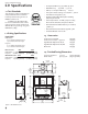
139435_A GZ 455 DV 8/28/12 1.0 Specifications • Steady State Efficiency: 74.5% NG / 76.7% LP • AFUE Efficiency: 71.3% NG / 75.1% LP • CSA P4. 1-02 Fireplace Efficiency: 1.1 Test Standards 66.05% • Factory Air Shutter Settings: Closed, NG / 3/16” LP This appliance complies with National Safety standards and is tested and listed by Intertek Testing Services of Middleton, Wisconsin.
2.0 General Information THIS APPLIANCE MUST BE INSTALLED AND MAINTAINED BY A QUALIFIED SERVICE AGENCY. DO NOT ATTEMPT TO ALTER OR MODIFY THE CONSTRUCTION OF THIS APPLIANCE OR ITS COMPONENTS. ANY MODIFICATION OR ALTERATION WILL VOID THE WARRANTY, CERTIFICATION AND LISTING OF THIS APPLIANCE. WARNING: FAILURE TO POSITION THE PARTS IN ACCORDANCE WITH THE DIAGRAMS HEREIN OR FAILURE TO USE ONLY PARTS SPECIFICALLY APPROVED WITH THIS APPLIANCE MAY RESULT IN PROPERTY DAMAGE OR PERSONAL INJURY.
139435_A GZ 455 DV 8/28/12 3.0 Safety Information Due to the high operating temperatures this appliance should be located out of traffic and away from furniture, draperies, etc. Maintain proper clearance to combustible mantels and fireplace trim. Children and adults should be alerted to the hazards of high surface temperatures and should stay away to avoid burns or clothing ignition.
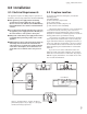
139435_A GZ 455 DV 8/28/12 4.0 Installation 4.1 Electrical Requirements 4.2 Fireplace Location This appliance requires 120 VAC, 4 amps for operation of the Blower, Accent Lamp, and Remote Control functionality. This appliance power supply must be electrically grounded in accordance with local codes or, in the absence of local codes, with the current ANSI/NFPA 70, National Electrical Code or CSA C22.1-Canadian Electrical Code.
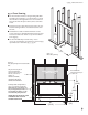
139435_A GZ 455 DV 8/28/12 4.3 Framing Requirements 4.3.1 Header Stand-off Assembly When installed, the Header Stand-off assembly will provide the required 46” combustible header height. 1. Detach the Header Stand-off assembly from its shipping position on the pallet. 2. Attach the Stand-off assembly upright to the front of the cabinet top using the four existing screws. Adjust the position of the Stand-off to accommodate the thickness of the non-combustible facing material. See Fig. 4.4. 3.
139435_A GZ 455 DV 8/28/12 4.3.2 Chase Framing The front header and chase ceiling framing will differ depending upon whether or not the fireplace is raised off of the floor. All height dimensions are based from the bottom of the fireplace cabinet, unless otherwise noted. Vertical vent runs require that 1 inch clearance to combustible framing members be maintained all around the vent.
139435_A GZ 455 DV 8/28/12 Fireplace Cabinet Header Stand-off Side Stand-off Non-combustible material Sheet Rock See fig. 5.2, note F on page 13 for required terminal clearances to the outside corner of building. Figure 4.7. Corner framing dimensions. 1 (25mm) 1/2 (13mm) Side Trim Depth Max. 6 (152) 27 (686) Side Wall 24 (508) Side Trim Figure 4.8 Parallel framing to side trim and wall.
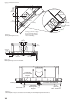
139435_A GZ 455 DV 8/28/12 Figure 4.10. Wall materials with Backer Plate installation, cut-away view. 4.4 Surround Treatments 4.4.1 Backer Plate The Backer Plate is useful for obscuring seams between the fireplace cabinet and the surrounding wall facing materials. The Face Plate is always used with the Backer Plate. Noncombustible Material Combustible Wall Facing Backer Plate 43” x 30 3/8” (109.2 cm x 77.1 cm) Finished Floor may be combustible material Install cabinet on min. 1 in.
139435_A GZ 455 DV 8/28/12 4.5 Vent Framing Clearances Combustible Chase Ceiling Combustible Ceiling Min. 24 (610mm) 32 1/2 (825mm) 2 (51) 53 3/4 46 (1365) (1168) 58 (1473) 1 (25) 32 7/8 (835) Min. 1 (25) Riser Figure 4.12. 5/8 Horiz2ntal termination with minimum vertical rise. Note minimum riser required to install Backer Plate. Figure 4.14. Local codes may require a listed wall thimble be installed according to manufacturer’s instructions. Dimensions may vary by manufacturer.
5.0 Venting Requirements 139435_A GZ 455 DV 8/28/12 5.1 Horizontal Termination There are three types of venting configurations approved for use with this fireplace. Any horizontally terminated vent system that includes Optimal Vent Configurations: 4/6 vent requires a 2 foot minimum vertical rise from • Vertical Venting / Vertical Termination • Vertical Venting / Horizontal Termination • Horizontal Venting / Horizontal Termination Natural Gas - 5/8 elbow directly to rear termination.
139435_A GZ 455 DV 8/28/12 Figure 5.2. Horizontal termination clearances. A = Clearance above grade, veranda, porch , deck, or balcony : 12 inches (30 cm) minimum. B = Clearance to window or door that may be opened: **Min. 9 inches, U.S. / *12 inches (30 cm) CAN. We recommend 12 in. minimum to prevent condensation on the window. C = Clearance to permanently closed window: **Min. 9 inches, U.S. / *12 inches (30 cm) CAN We recommend 12 in.
139435_A GZ 455 DV 8/28/12 5.2 Vertical Termination This appliance can be vertically vented through a roof or ceiling following these guidelines: The termination must fall within any of the Zones defined in the termination diagram, fig. 5.5 on page 15. Steep roofs, nearby trees, or predominantly windy conditions, can promote poor draft or down draft conditions. In such cases, an increase to the height of the vent may improve performance.
139435_A GZ 455 DV 8/28/12 VERTI CAL RUN NOT A P PROVED ZONE D - = Less Restriction I N TA K E RESTRICTION INSTALLED + = More Restriction Adjustment Screw EXHAUST = 1/2 TO FULL RESTRICTION ZONE D ZONE C B ZONE ZONE A Locking Screw ZONE C I N TA K E R E S T R I C T I O N I N S TA L L E D EXHAUST = 1/2 to NO RESTRICTION NO RESTRICTION NOT APPROVED
139435_A GZ 455 DV 8/28/12 6.0 Fireplace Assembly 6.1 Glass Frame Removal The glass frame is removed by disengaging six compression latches. There are two upper, two lower, and one at each side. See fig. 6.1. Simply pull the latch handle out to release each latch. Disengage the lower and side latches before releasing the upper latches. 6.
139435_A GZ 455 DV 8/28/12 6.3 Connecting the Gas Supply Gas Supply Requirements ALL INSTALLATIONS MUST COMPLY WITH LOCAL CODE OR IN THE ABSENCE OF LOCAL CODE, MUST COMPLY WITH THE MOST RECENT EDITION OF THE NATIONAL FUEL GAS CODE ANSI Z223.1/NFPA 54 OR CAN-B149. Shut-off Valve A shut-off valve must be installed upstream of the gas control valve. This allows for the disconnection of the fireplace for servicing and maintenance. See Fig. 6.3.
139435_A GZ 455 DV 8/28/12 6.4 Testing Gas Pressure E - Inlet Proper gas pressure provides a consistent flow of gas to the appliance and is instrumental in checking for gas leaks. There are two pressure test points on the front of the fireplace control valve where test gauge connections are made. See Fig. 6.4. Gauge connections are identified by: • E for inlet or supply pressure ( the amount of gas coming to the valve.
139435_A GZ 455 DV 8/28/12 6.5.1 Fuel Conversion Procedure 1. Turn off gas supply to the appliance and disconnect from electrical power source. 3. Remove the Front Apron panel (fig. 6.5-A). Use a 1/4” socket driver to remove the two side screws and only loosen the five bottom screws. 4. Remove the Controls Heat Shield (fig. 6.5-B). Reach under the firebox to loosen the Air Shutter wing nut located above the valve compartment (fig. 6.6). 5. Lift the Burner Riser/Media Tray (fig. 6.5-C) out of the firebox.
139435_A GZ 455 DV 8/28/12 Fuel Conversion, cont’d. 10.Replace the Burner Plate. Engage the burner tube with the Air Shutter assembly. Engage the slots on the right end with the support brackets. 11. Replace the Valve Regulator. Using a Torx T-20 screwdriver, remove the two screws from the front of the regulator, (fig.6.10). Disconnect the motor lead at the splice connector and replace the regulator components with those from the conversion kit. Reconnect the motor lead. 12.
139435_A GZ 455 DV 8/28/12 6.6 Firebox Liner Installation Mirrored Reflective Glass Panels - 157413 Black Reflective Glass Panels - 157414 Desert Sand Refractory Panels - 157407 6.6.1 Glass Firebox Panels 1. Unpack the glass panels and inspect. Notify your dealer of any damage. Do not install damaged panels. 2. If it has not already been removed, lift the burner media tray and skirt assembly out of the firebox. 3.
139435_A GZ 455 DV 8/28/12 6.7 Install Burner Media 6.7.1 StarFire Glass 6.7.2 Tumbled Stones - 157417 Contents: Contents: • 157415 Clear/White StarFire Glass, 3 lbs. • 157416 Black StarFire Glass, 3 lbs. 1. Use safety gloves and handle the glass carefully. Spread the stones evenly over the media tray. Be careful to retrieve any stones that may drop onto the burner itself. You do not need to use all of the stones. • Stones, Qty: 125 1.
139435_A GZ 455 DV 8/28/12 6.8 Surround Assembly Centering Plate 6.8.1 Face Plate Bracket Adjustments 1. Use a 1/4” socket driver or flat screw driver to loosen the two sheet metal screws that secure the Centering Plate (Fig. 6.15). Pull the Centering Plate out to the depth appropriate to clear the finished wall surface. Access Ports 2. Loosen the wing nuts on the two side Adjustment Brackets and pull them out the same distance as the Centering Plate. 6.8.2 Optional Backer Plate Installation 1.
139435_A GZ 455 DV 8/28/12 6.9 Initial System Check The burner and fan control system consists of the following built-in or supplied components: 1) Remote Transmitter - 3, AAA batteries preinstalled 2) Remote Receiver - 4, AA backup batteries preinstalled 3) Fan Control Module - switched 4) Pilot Mode Switch All internal connections have been made at the factory. The remote controls are preprogramed and the entire system tested. NOTE: Check the build date on the shipping crate label.
139435_A GZ 455 DV 8/28/12 6.10.1 Flame Appearance / Air Shutter Adjustment WARNING: AIR SHUTTER ADJUSTMENTS SHOULD ONLY BE PERFORMED BY A QUALIFIED, PROFESSIONAL SERVICE TECHNICIAN. Locate the Primary Air Shutter control under the firebox floor. The shutter is set at the at the factory for Natural gas. This will give good results in the majority of installation configurations, however, it may be necessary to adjust it to get the best flame picture depending upon the specific venting configuration.
7.0 Operation 7.1 Features Overview The Proflame GTMFS system is a modular remote control system that directs the functions of the Atra GZ 455 gas freestanding unit. It is configured to control the on/off operation both manually and thermostatically, with standard and “Smart” thermostat features. It will also control flame modulation, manual flame control, fan on/off and speed and on/off of accent lighting features.
139435_A GZ 455 DV 8/28/12 REMOTE RECEIVER Figure 7.1. GZ 455 DV Control Switches. 7.2.2 Remote Receiver The Remote Receiver, located in the control compartment, is powered through the Fan Control Module and AA back-up batteries. The Receiver can be set to one of three different positions. See fig. 7.1. ON - this is a manual override allowing the burner to function without remote control. The ignitor will spark within 3 seconds .
139435_A GZ 455 DV 8/28/12 Remote Transmitter Controls, cont’d. Temperature Indication Display With the transmitter in the OFF position, press the Thermostat Key and the Mode Key at the same time. The display screen will show the current room temperature cycling between Fahrenheit and Celsius indicators each time the keys are pressed simultaneously. See fig. 7.4. Figure 7.4. Room temperature readings Turn on the Burner Press the ON/OFF Key on the Transmitter.
139435_A GZ 455 DV 8/28/12 SMART Thermostat Function This function adjusts the flame intensity according to the difference in the Set Point temperature and the actual room temperature. As the room temperature gets closer to the Set Point, the Smart Function will modulate flame intensity down. To activate this function, press the Thermostat Key until the word “SMART” appears to the right of the thermometer bulb icon. Fig. 7.12. To adjust the temperature, press the Up or Down Arrow Figure 7.12.
8.0 Maintenance This appliance and its venting system should be inspected before use and at least annually by a qualified service technician. WARNING! THE IGNITION SYSTEM OF THIS APPLIANCE CARRIES LIVE VOLTAGE. ALWAYS TURN “OFF “ THE MAIN GAS SUPPLY AND DISCONNECT THE POWER SOURCE BEFORE PERFORMING ANY MAINTENANCE PROCEDURE. TURN “OFF “ THE MAIN GAS SUPPLY AND DISCONNECT THE POWER SUPPLY TO THE APPLIANCE BEFORE REPLACING BATTERIES. 8.1 Annual Cleaning 8.1.
139435_A GZ 455 DV 8/28/12 5. Beginning at the midpoint of the lower edge, apply the new gasket around the glass panel, with the adhesive side inside and the thicker portion on the outside. DO NOT STRETCH THE GASKET MATERIAL. Trim off any excess, leaving a 1/2” overlap as shown in fig. 8.1. 6. Lay the glass panel within the glass frame and press the tabs back down or press the clips in place as shown in fig. 8.2 3. Install 3, AAA batteries in the Transmitter bay and push the ON button.
139435_A GZ 455 DV 8/28/12 Figure 8.5.
139435_A GZ 455 DV 8/28/12 9.0 Atra GZ 455 DV Replacement Parts Use only genuine Atra Replacement Parts available from your local Authorized Jøtul Dealer or by contacting: Jøtul North America 55 Hutcherson Dr. Gorham, ME 04038 207 591-6601 Figure 9.1 Gas Train and Controls Assembly 33 34 32 31 No. Part No.
139435_A GZ 455 DV 8/28/12 No. Part No. Description 1 224725 Control Box Air Diverter 2 224376 Pilot Shield 3 224377 Burner Air Deflector 4 224422 Air Intake Restrictor 5 22423792 Burner Skirt, Matte Black 224741 Burner Skirt, Stainless Steel 22424292 Burner Skirt Rear Panel, MB 224742 Burner Skirt Rear Panel, Stainless Steel 22423892 Media Tray, Matte Black 224743 Media Tray, Stainless Steel 6 7 Figure 9.2. GZ 455 DV Burner Skirt Parts No. Part No.
139435_A GZ 455 DV 8/28/12 9 8 13 7 6 5 10 3 4 14 11 2 12 1 15 Figure 9.4. GZ 455 DV Fireplace Cabinet Parts No. Part No. Description 1 117917 Screw, #8 1/2” SMS 2 224722 Blower Access Panel 3 224474 Blower Mounting Bracket 4 222072 Blower 5 224247 Rear Cabinet Panel 6 224249 Top Cabinet Panel 7 8 224428 224427 Top Vertical Support Top Vertical Standoff 36 No. 9 10 11 12 13 14 15 Part No.
139435_A GZ 455 DV 8/28/12 10.0 Appendix 10.1 Blower Installation Figure 10.1 Retainer Bar This blower must be electrically grounded in accordance with local codes or, in the absence of local codes, with the current ANSI/NFPA 70, National Electrical Code or CSA C22.1-Canadian Electrical Code. Be certain the blower motor is securely fastened to the mounting frame on the stove. Always disconnect the power supply to the stove before performing any service on the blower.
139435_A GZ 455 DV 8/28/12 10.2 Approved Vent Manufacturers The Atra GZ 455 DV fireplace is approved for installation with direct vent chimney components supplied by the following manufacturers: Simpson Dura-Vent, Inc. P.O. Box 1510 Vacaville, CA 95696-1510 800-835-4429 Selkirk Corporation 1301 W. President George Bush Hwy, Suite 330 Richardson, TX 75080-1139 800-992-8368 American Metal Products (Amerivent) 8601 Hacks Cross Rd.
139435_A GZ 455 DV 8/28/12 This page is intentionally blank.
139435_A GZ 455 DV 8/28/12 This page is intentionally blank.
139435_A GZ 455 DV 8/28/12 This page is intentionally blank.
139435_A GZ 455 DV 8/28/12 11.0 Jøtul Group Gas Product Limited Warranty This warranty policy applies to gas products identified by Jøtul, Scan, and Atra trade names, as set forth below. A. Cast Iron, Steel Doors, Surround Components, Firebox: Jøtul North America Inc.
139435_A GZ 455 DV 8/28/12 LIGHTING INSTRUCTIONS FOR YOUR SAFETY, READ BEFORE LIGHTING. WARNING: IF YOU DO NOT FOLLOW THESE INSTRUCTIONS EXACTLY, A FIRE OR EXPLOSION MAY RESULT CAUSING PROPERTY DAMAGE, PERSONAL INJURY, OR LOSS OF LIFE. A. This appliance is equipped with an ignition device which automatically lights the pilot. Do not try to light the pilot by hand. B. BEFORE LIGHTING, smell all around the appliance area for gas.
139435_A GZ 455 DV 8/28/12 August 2012 139435_A This appliance must be installed in conformance with local and national building regulations. Before beginning the installation, it is important that these instructions be carefully read and understood. Atra maintains a policy of continual product development. Consequently, products may differ in specification, color or type of accessories from those illustrated or described in various publications. Atra vise sans cesse a ameliorer ses produits.