
Owner`s manual


13
139435_A GZ 455 DV 8/28/12
5.0 Venting Requirements
There are three types of venting configurations approved
for use with this fireplace.
•VerticalVenting/VerticalTermination
•VerticalVenting/HorizontalTermination
•HorizontalVenting/HorizontalTermination
OptimalVentConfigurations:
NaturalGas-5/8elbowdirectlytoreartermination.
Propane-4/6vent,4ft.verticalrisetoreartermination.
Thisapplianceisapprovedforusewiththe4/6and
5/8directventsystemsmanufacturedbythecompa-
nies listed in the Appendix on page 38.
A4/6VentAdaptorisincludedwiththeappliance.
Use parts of one manufacturer only - DO NOT MIX
VENTCOMPONENTSFROMDIFFERENTMANUFACTUR-
ERSWITHINTHESAMESYSTEM.
Installation of any components not manufactured
or approved by Atra or failure to meet all clearance
requirements will void all warranties and could result
inpropertydamageorbodilyinjury.
The approved vent configurations described in this
manual are derived from extensive testing under con-
trolled laboratory conditions. Gas appliance performance
can be negatively affected by variables present in the in-
stallation environment, i.e.; atmospheric pressure, strong
prevailingwinds,adjacentstructuresandtrees,snow
accumulation, etc. These conditions should be taken into
consideration by the installer and fireplace owner when
planning the vent system design.
IMPORTANT
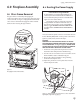
Joint Sealing Requirement
Simpson Dura-Vent:
• Apply1/8”beadofhigh-
temperature, non-silicone
sealant or Mil-Pak® to the
male section of the inner
pipe. The cement should
form a seal between the
two inner pipe sections. See
fig. 5.1 and the vent manu-
facturer’s instructions.
• Nevermodifyanyventingcomponent,oruseany
damaged venting product.
• Thegasapplianceandventsystemmustbevented
directly to the outside of the building and never at-
tached to a chimney serving a solid fuel or gas burning
appliance. Each direct vent gas appliance must have
itsownseparateventsystem.Commonventsystems
are prohibited.
• Ifventingsystemisdisassembledforanyreason,rein-
stall per the manufacturer’s instructions provided for
the initial installation.
Fig. 5.1.
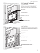
5.1HorizontalTermination
Any horizontally terminated vent system that includes
a vertical run must terminate within one of the Zones
defined in the diagram in fig. 5.5. See page 15 for
important information regarding exhaust restriction
adjustments.
4/6ventrequiresa2footminimum vertical rise from
thetopventcollar.Seefig.4.11.
5/8ventmaybedirectedtoahorizontaltermination
with an 90° elbow straight off the top vent collar. See
fig.4.10.Themaximumhorizontalrun,withnovertical
rise,is4feet.
Amaximumofthree90°orsix45°elbowsmaybe
used in a horizontally terminated, top exit vent sys-
tem.Wheneverpossible,use45°elbowsinsteada90°
elbow as they offer less restriction to the flow of flue
gases and intake air.
Reducetheoverallhorizontalrunby4feetforeach
90°elbow,and2feetforeach45°elbow.
When two or more elbows are used in a horizontal run,
a less restricted setting may be more effective than that
indicated by the termination zone diagram.
The termination cap must not be recessed into the
wallorsiding. Do not fill air space in wall around termina-
tion cap with any type of insulation.
Wall Cut-out: 4/6ventrequiresa10”x10”minimum
square hole. 5/8ventrequiresaminimum11”X11”
square hole. These cut-outs are adequate for proper pipe
clearance through a wall provided the vent is positioned
tomaintain2”minimumclearanceatthetop.A1”-inch
minimum clearance must be maintained to combustible
material around the other sides. The wall cut-out must
be fully framed-in.
Anyhorizontalventrunmustbelevelorhavea1/4”
rise for every foot of run toward the termination cap.
Ventmaynotdirectdownwardatanypoint.
All horizontal terminations must comply with the clear-
ancespecificationstoadjacentstructuresasindicatedin
fig. 5.2.
Installation of a Vinyl Siding Standoff is required to
prevent damage to vinyl siding between the vent cap
and the exterior wall.
Ahorizontalterminationcapmustmaintaina3inchclear-
ancetoanyoverheadcombustiblematerialsthatproject2
1/2inchesorless.Projectionsexceeding21/2inchesrequire
a minimum 12 inch clearance to the edge of the vent termi-
nation. See fig. 5.3.
Vinylsidingprojectionsrequireadefaultclearanceof18
inches to the top of the vent terminal.