
Owner`s manual

21
139435_A GZ 455 DV 8/28/12
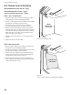
6.5HighAltitudeAdjustment
The decreased atmospheric pressure of higher altitudes
affects the heat value of gaseous fuels. Most gas
suppliers derate the gas intended for use at elevations
above2000feet.Checkwithyourgassupplierbefore
performingderateadjustmenttotheburner.
Thisappliancemaybeadjustedforaltitudeover2000ft.
(610 - 1371 m) for natural gas or propane.
If the gas supplier does not derate fuels, install High
AltitudeAdjustmentKit157430forPropaneandKit157431
for Natural gas.
U.S&Canadaper
ANSIZ21.88-2009•CSA2.33-2009,CAN/CGA2.17
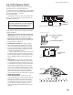
Forinstallationsfrom610-1370meters(2000-4550ft.)
theorificesizes(DMS)fornaturalandpropanegasare
#41and#53respectively.Seedataplateforadditional
information. For high altitude installations consult the
localgasdistributorortheauthorityhavingjurisdiction
for proper rating methods. If the installer must convert
theunittoadjustforvaryingaltitudes,theinformation
sticker must be filled out and applied to the appliance at
the time of the conversion.
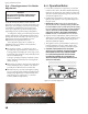
6.5.1 Derating Procedure
1. Confirmthattheinjectoridentificationstampconformstothe
sizespecificationnotedabove.
2. Usea1/2”or13mmdeepsockettoremovetheoriginalorifice
and replace it with the one provided in the kit appropriate for
gas type. See fig.6.8, page 20.
3. Replacetheburnerandburnerskirt.
4. Conductgasleakandgaspressuretestsasdetailedonpages
16-17 of this manual.
5. Conductsystemcheckandflamepictureadjustments
asspecifiedpages24-25.
6. Fill out the appropriate information and apply the high
altitude conversion label provided to the rating plate
on the appliance. See fig. 6.10.
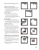
Figure 6.10. Hi gh Altitude Conversion Label.
This appliance has been converted for use at an
altitude of___________ .
Orifice Size: __________ Manifold Press. _______
InputBtu/Hr._________FuelType___________
Date:___/___/___Convertedby:_____________
Cetappreeilaétéconvertiau_____Injecteur_____
Pressionàlatubulured’alimentation___________
Déoitcalorifique___________
Cet appareil est equippé pour des altitudes compries
entre0et2000pieds(0-610m)seulement.
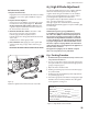
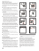
Fuel Conversion, cont’d.
Figure 6.9.
Replace the regulator tower and reconnect the motor leads.
10.ReplacetheBurnerPlate.
Engage the burner tube with the Air Shutter assembly.
Engage the slots on the right end with the support
brackets.
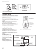
11. Replace the Valve Regulator.
Using a Torx T-20 screwdriver, remove the two screws
from the front of the regulator, (fig.6.10). Disconnect
the motor lead at the splice connector and replace the
regulator components with those from the conversion
kit.Reconnectthemotorlead.
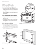
12. Install the identification labels to the valve so that
they can be seen by any service technician.
LabelA:applytovalvecompartmentfloor.
LabelB:applytotheratingplateattachedtotheback
of the stove.
SmallConversionLabel:applytovalve.
13.Reassemblethestove,apply gas to the system and
check for leaks using a soapy water solution or gas
detector.
NEVER USE AN OPEN FLAME TO CHECK FOR GAS LEAKS.