
Owner`s manual

25
139435_A GZ 455 DV 8/28/12
6.9 Initial System Check
The burner and fan control system consists of the
following built-in or supplied components:
1)RemoteTransmitter-3,AAAbatteriespreinstalled
2)RemoteReceiver-4,AAbackupbatteriespreinstalled
3)FanControlModule-switched
4)PilotModeSwitch
All internal connections have been made at the
factory. The remote controls are preprogramed and
the entire system tested.
Follow this procedure for the initial system check fol
lowing installation:
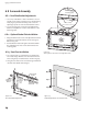
1. TurntheFanControlModulerockerswitchtothe
ON position, fig. 6.18. It is located in the right side
compartment,undertheAccentLampcontrol.
2. SlidetheRemoteReceiverswitchtotheONposi-
tion. The ignitor will generate spark in either IPI or
CPIpilotmodes.Seefig.6.19.
3. PURGING THE GAS LINE: Open the gas supply
valve. When lighting the appliance for the first
time it will take a few moments to clear the gas
line of air. Once the purge is complete, the pilot
light will ignite. Opening the inlet pressure test
point will help bleed the gas line.
When purging the line, the system may go into
lock-down mode. To continue purging, move the
ReceiverswitchtoOFFfor15seconds,thenswitch
backtoREMOTEorONandtrytolightthepilot
again.
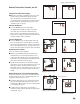
4. PILOT FLAME: The pilot flame should be steady
-not lifting or floating. The flame should be blue
in color around the pilot hood, with traces of yel-
low toward the outer edges. It is important that
thepilotflameengulfthetop1/8”oftheflame
sensor.Thepilotflameshouldprojectoutofthe
pilothood1”frombothportsextendingtoreach
the burner plate ports. See fig. 6.20 . The pilot
flamecanbetunedbyturningtheadjustment
screwlocatedonthefrontofthevalve.Seefig.6.4.
5. INSTALLER PLEASE NOTE:
CHECK FUNCTIONALITY. The burner, remote
control and fan functions have each been tested
at the factory. However, it is important to run
through each function and be sure to familiarize
the homeowner with the operation procedures.
See the Operation section on pages 27-30. for
detailsregardingRemoteControlfunctionsand
settings.
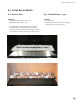
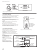
Figure 6.20. Correct Pilot flame pattern.
Ignitor
Flame Sensor
Carry-over Ports
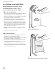
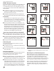
Figure 6.19. Initial system settings.
CPI/ContinuousPilotIgnition
(Standing Pilot)
IPI/IntermittentPilotIgnition
OR
Remote Receiver
Switch
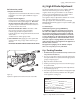
NOTE: Check the build date on the shipping
crate label. If it has been more than 6 months
sincethebuilddate,bepreparedtoreplace
the Receiver and Transmitter batteries.
= POWER ON
= POWER OFF
Open outlet
- not used
Figure 6.18. Fan Control Module power switch.
to
Fan
to
AccentLamp