
Owner`s manual

32
139435_A GZ 455 DV 8/28/12
8.5BatteryReplacement
Battery life depends on many variables; the quality of
the batteries, frequency of remote use, and mode of
pilotoperation.Keepasupplyofgoodqualitybatteries
on hand to be assured of functional continuity in the
event of a power failure.
TheRemoteTransmitterbatteriesareeasilyaccessed
through the tabbed cover plate. Be sure to orient the
batteries for correct polarity as indicated in the battery
compartment.
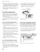
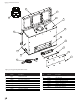
8.5.1ReceiverBatteryReplacement
It will be necessary to remove the left side compartment
door to access the battery cover plate.
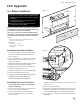
1. Removethelowerdoorhingebracket(one,10mm
nut). The door will drop out of the upper hinge
bracket.
2.PushthesliderswitchintotheOFFposition.Remove
theReceivercoverplatescrewsandprythecover
plate with slider switch off of the battery box. See fig.
8.3..
3. Install4AAbatteriesintothereceiverbay.Notethe
polarity of the batteries and insert into the battery
bayasindicatedonthebaycover(+/-).
4.WiththeswitchstillintheOFFposition,alignthe
slider switch with the switch stem and snap the cover
plate back onto the battery box.
5.ReplacetheReceivercoverplatescrews.
6. ReplacetheCompartmentDoorandlowerhinge
bracket.
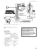
8.6AccentLampReplacement
Handlethereplacementbulbwithgloves.Skinoilswill
cause the bulb to fail prematurely. If you touch the bulb
withyourbarefingers,wipeitcleanwithasoftcloth.
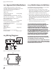
1. Removelampcompartmentcoverplate.Seefig.8.4.
.
2. Removethetwophillipsscrewsfromthebulbsocket
to access the bulb. Pull the bulb out of the housing.
3. Plug the new bulb into the socket and re-install the
cover plate into the lamp housing.
8.5.2InitializingtheRemoteControl
Each time you replace the batteries, you may need to
initializecommunicationbetweentheReceiverandthe
Transmitter.
1. PlacethesliderswitchintheREMOTEposition.
2. InserttheendofapaperclipintotheholemarkedPRG
ontheReceivercover.TheReceiverwill“beep”three(3)
times to indicate that it is ready to synchronize with
the Transmitter.
Figure 8.4. Remove cover plate to access lamp bulb.
Use222943Bulb,130V/50W
LampCoverplate
Figure 8.3
Receiver battery access.
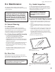
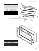
5. Beginning at the midpoint of the lower edge, apply
the new gasket around the glass panel, with the adhe-
sive side inside and the thicker portion on the outside.
DONOTSTRETCHTHEGASKETMATERIAL.Trimoffany
excess,leavinga1/2”overlapasshowninfig.8.1.
6.Laytheglasspanelwithintheglassframeandpress
the tabs back down or press the clips in place as
shown in fig. 8.2
3. Install 3, AAA batteries in the Transmitter bay and
pushtheONbutton.TheReceiverwill“beep”four
times to indicate the Transmitter’s command is
accepted and sets to the particular code of that
Transmitter. The system is now initialized.