
Owner`s manual

8
139435_A GZ 455 DV 8/28/12
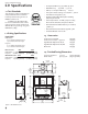
4.3 Framing Requirements
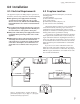
4.3.1HeaderStand-offAssembly
When installed, the Header Stand-off assembly will
providetherequired46”combustibleheaderheight.
1. Detach the Header Stand-off assembly from its
shipping position on the pallet.
2. Attach the Stand-off assembly upright to the front of
thecabinettopusingthefourexistingscrews.Adjust
the position of the Stand-off to accommodate the
thickness of the non-combustible facing material. See
Fig.4.4.
3. Detach the Header Support Brackets from their
shippingpositionsonthestand-offstuds.Fig.4.2.
Attach the Support Brackets to the rear of the two
center framing members using the sheet metal
screws previously removed. Orient the brackets with
the slotted ends attached to the top of the cabinet as
shown.
5. Bend the nailing flanges on the two Side Stand-off
Brackets out 90° from the flat shipping position and
adjusteachbracketasnecessarytoaccommodatethe
thickness of the non-combustible face material. See Figs.
4.3.and4.4.
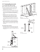
NOTE: FINISHED WALL THICKNESS
The fireplace cabinet can accommodate finished wall
materialthicknessuptoatotalof31/4”byadjusting
the surround support brackets to maximum extension.
SeeFig.4.4.
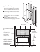
Figure 4.2.
Install Header Stand-off brackets.
Installed
Orientation
Shipping
Position
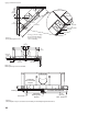
Figure 4.3.
Side stand-off orientation.
Figure 4.4.
Maximum framing stand-off and surround bracket adjustment.