CyberChiller Series Installation, Operation & Maintenance Manual (©October, 2006)
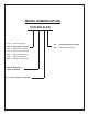
CyberChiller Series Installation, Operation & Maintenance Manual MODEL NOMENCLATURE CCH-330-D-AR OHS = Overhead System CCH = CyberChiller System VFS = Vertical Floor System AR = Air-Cooled Remote (Split) W/G = Water/Glycol Cooled FCS = Floor Console System GPS = Glycol Pump System COS = CyberONE System MCS = Modular Cyber System Nominal Capacity in 1,000’s of BTU/Hr D ( ) = Dual (Two) Circuit System (©October, 2006)
CyberChiller Series Installation, Operation & Maintenance Manual TABLE OF CONTENTS 1.0 Introduction ....................................... 1-1 1.1 1.2 1.2.1 1.2.2 1.2.3 1.2.4 1.3 1.4 1.4.1 1.4.2 General ...................................................... 1-1 Product Description ................................... 1-1 Capabilities and Features .......................... 1-1 Application Ranges .................................... 1-1 General Design ..........................................
CyberChiller Series Installation, Operation & Maintenance Manual List of Figures Figure 1- Typical Layout ........................................ 1-2 Figure 2- Typical Installation .................................. 2-1 Figure 3- Typical Piping Air Cooled Systems ......... 2-3 Figure 4- Typical Piping Water/Glycol Cooled Systems ................................................ 2-5 Figure 5- Sample Nameplate ................................. 2-6 Figure 6- Electric Box ...........................
CyberChiller Series Installation, Operation & Maintenance Manual 1.0 INTRODUCTION 1.1 General Congratulations, the CyberChiller™ floor mounted liquid chiller system covered by this manual is designed and manufactured by Stulz Air Technology Systems, Inc. (SATS) using the latest, state-of-the-art control technology. Recognized as a world leader, SATS provides precision cooling systems with the highest quality craftsmanship using the finest materials available in the industry.
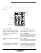
CyberChiller Series Installation, Operation & Maintenance Manual 1.2.3 General Design The CyberChiller is divided into 3 areas; a pump section, a refrigeration section and an electrical section. The housing is a frame type construction. Figure 1 depicts the internal layout of the unit and the location of the major components.
CyberChiller Series Installation, Operation & Maintenance Manual cycle, one scroll remains stationary while the other scroll orbits around the first. As this motion occurs, gas is drawn into the scrolls and moved in increasingly smaller pockets toward the center. At this point, the gas, now compressed to a high pressure, is discharged from a port in the center if the fixed scroll. During each orbit, several pockets of gas are compressed simultaneously, creating smooth, nearly continuous compression.
CyberChiller Series Installation, Operation & Maintenance Manual 1.3 Product Warranty SATS offers a two year standard limited warranty as stated below. Additionally an extended warranty may be purchased on the unit's compressors. Consult the factory to verify if the extended compressor warranty was purchased for your system. The compressor warranty as stated on the next page will be sent with your unit and should be retained for future reference.
CyberChiller Series Installation, Operation & Maintenance Manual Optional Limited Extended Warranty (5 Years Total) Stulz Air Technology Systems, Inc., warrants to the original buyer of its product that the compressor(s) listed below are warranted for parts replacement (not including labor) for extended period of 4 years from the date of expiration of the standard equipment warranty.
CyberChiller Series Installation, Operation & Maintenance Manual 1.4 Safety 1.4.1 General Stulz Air Technology Systems, Inc. uses NOTES along with CAUTION and WARNING symbols throughout this manual to draw your attention to important operational and safety information. A bold text NOTE marks a short message in the information to alert you to an important detail. A bold text CAUTION safety alert appears with information that is important for protecting your equipment and performance.
CyberChiller Series Installation, Operation & Maintenance Manual CAUTION All personnel working on or near equipment should be familiar with hazards associated with electrical maintenance. Safety placards/stickers have been placed on the unit to call attention to all personal and equipment damage hazard areas. CAUTION Ensure the unit is properly phased. Improper phasing can cause severe damage to the compressor. WARNING Refrigerant (R-22 or R-407C) is used with this equipment.
CyberChiller Series Installation, Operation & Maintenance Manual 2.0 NOTE INSTALLATION 2.1 Receiving the Equipment Your CyberChiller system has been tested and inspected prior to shipment. To ensure that your equipment has been received in excellent condition, make a visual inspection of the equipment immediately upon delivery. Carefully remove the shipping container and all protective packaging. Open the access doors and thoroughly inspect the unit interior for any signs of transit-incurred damage.
CyberChiller Series Installation, Operation & Maintenance Manual The following general requirements should be considered during installation: NOTE Equipment must be level to operate properly. 2.4.1 Indoor Equipment The CyberChiller system uses a frame and panel construction for unit rigidity and full service accessibility while the unit is mounted in place. The unit is designed to be located directly on top of the floor or on a raised floor installation.
CyberChiller Series Installation, Operation & Maintenance Manual 2.5 Piping Connections 2.5.1 Process Supply Fluid Lines Coolant fluid supply and return lines are connected from the equipment being cooled to the CyberChiller via copper sweat fittings provided in the pump section. 2.5.2 Refrigerant 2.5.2.1 Split Air Cooled Systems Split air-cooled systems with a remote condenser will require field refrigeration piping. (See Figure 3.
CyberChiller Series Installation, Operation & Maintenance Manual NOTE In the following (3) charts, the line sizes represent the sizing for individual refrigeration circuits. CyberChiller units have two separate pairs of refrigeration lines. (One per compressor.) Equivalent Length (ft) of Straight Pipe OD (In.) Globe Line Size Valve Angle Valve 90º Elbow 45º Elbow Tee Line Tee Branch 1/2 9.0 5.0 0.9 0.4 0.6 2.0 5/8 12 6.0 1.0 0.5 0.8 2.5 7/8 15 8.0 1.5 0.7 1.0 3.
CyberChiller Series Installation, Operation & Maintenance Manual EXPANSION TANK (MUST BE INSTALLED AT THE HIGHEST POINT IN THE SYSTEM.) AIRTROL FITTING VALVE SHUT-OFF REMOTE DRYCOOLER WATER/GLYCOL COOLED CONDENSER SHUT-OFF SHUT-OFF ~ FLOW BYPASS VALVE REGULATOR AQUASTAT PUMP PACKAGE VALVE STRAINER SHUT-OFF VALVE UNION CHECK VALVE SHUT-OFF UNION PUMP Figure 4- Typical Piping Water/Glycol Cooled System WARNING Glycol is hazardous.
CyberChiller Series Installation, Operation & Maintenance Manual CKT BKR) for circuit protection. The unit's nameplate is located inside the cabinet within the electrical box. NOTE If the nameplate states MAX FUSE/CKT BKR, it is required to utilize fuses or HACR type circuit breakers to protect the system. Other protection devices are not allowed based upon the product listing. Each unit is provided with terminals for all required field-wiring connections, (supplied by others).
CyberChiller Series Installation, Operation & Maintenance Manual Each unit is provided with main power and control terminal positions for connection of the field-wiring. The opening for the conduit is located in the floor of the cabinet. A label stating "MAIN POWER INPUT" is in close proximity. The main power wires are terminated at the line side of the service disconnect switch located within the electric box. (See Figure 6.
CyberChiller Series Installation, Operation & Maintenance Manual MAIN PO 208-575V INTERCONNECTING FIELD WIRING (TO BE INSTALLED IN ACCORDANCE WITH NFPA 70, N.E.C.) MAIN POWER SUPPLY 208-575V/3PH/60Hz 24VAC AIR COOLED CONDENSER INTERCONNECTING FIELD WIRING (TO BE INSTALLED IN ACCORDANCE WITH NFPA 70, N.E.C.) Figure 7- Interconnecting Field Wiring Remote Condenser 2.6.4.1 Air-Cooled Split System Remote Condenser 2.6.4.2 Glycol Systems With Outdoor Fluid Pump Package See Figure 7.
CyberChiller Series Installation, Operation & Maintenance Manual MAIN POWER SUPPLY 208-575V/3PH/60Hz MAIN POWER SUPPLY 208-575V/3PH/60Hz INTERCONNECTING FIELD WIRING (TO BE INSTALLED IN ACCORDANCE WITH NFPA 70, N.E.C.) DRYCOOLER (GLYCOL UNITS ONLY) INTERCONNECTING FIELD WIRING (TO BE INSTALLED IN ACCORDANCE WITH NFPA 70, N.E.C.) 24VAC BOX GPS PUMP PACKAGE (GLYCOL UNITS ONLY) Figure 8- Interconnecting Field Wiring Glycol Systems 2.7 System Settings and Adjustments 2.7.
CyberChiller Series Installation, Operation & Maintenance Manual 2. Open the vent valve at highest point of the system. 6. Re-open isolation valves. 3. Open the water source and run until the water solution is discharging from the vent with minimal signs of foaming due to air in the system. 7. Resume unit operation. Repeat steps 1 – 6 every 30 minutes for first 3 hours operation. 2.7.2 4. Allow pump to run until 30 psig is indicated on the pressure gauge at the pump inlet fitting. 5.
CyberChiller Series Installation, Operation & Maintenance Manual sub-cooling temperature should be approximately 10-20 ºF. CAUTION A proper vacuum must be drawn on the refrigerant system prior to charging. If this is not done the refrigerant will combine with the moisture in the pipes to form an acid that will eventually cause compressor failure. NOTE Under cold climate conditions it is recommended to do the following: 6. FINE TUNING THE SYSTEM CHARGE 2.7.3.
CyberChiller Series Installation, Operation & Maintenance Manual CAUTION POE oil is used in systems with R-407C refrigerant. POE oil quickly absorbs moisture when exposed to air. High POE oil moisture levels react with refrigerant to form acid, which results in system contamination. Keep entire system sealed as much as possible and minimize exposure of POE oil to outside air. Familiarize yourself with the charging procedures discussed in section 2.7.3 of this manual.
CyberChiller Series Installation, Operation & Maintenance Manual 2.7.6 Head Pressure Controls 2.7.7 2.7.6.1 Air-Cooled Systems 2.7.6.1.1 Condenser Fan Speed CyberChiller units utilize a thermal expansion valve (TEV) to control the flow of refrigerant entering the evaporator in order to maintain a constant superheat of the refrigerant vapor at the outlet of the evaporator. Superheat is the difference between the refrigerant vapor temperature and its saturation temperature at that pressure.
CyberChiller Series Installation, Operation & Maintenance Manual 2.8 Refrigerant Characteristics 2.8.2 2.8.1 Pressure/Temperature Settings The following refrigerant vapor pressure tables are provided for reference. The following chart is provided to assist with the normal settings of the system for R-22 and R407C refrigerant. Where applicable, minimum and maximum settings are given along with normal operating pressures. Pressure/Temperature Settings For R-22 & R407C Normal Min. Max.
CyberChiller Series Installation, Operation & Maintenance Manual 3.0 START-UP/COMMISSIONING 3.1 Operation For new installations, ensure the unit is ready to operate by going through the Checklist for Completed Installation, located in Appendix A, prior to start-up. NOTE A Warranty Registration and Start-Up Checklist is provided with the unit data package. It should be completed during start-up and sent to SATS.
CyberChiller Series Installation, Operation & Maintenance Manual supplied to the equipment. The flow switch senses the coolant flow in the system. When the pump is operating, the coolant flow in the piping actuates the flow switch. The switch will signal the system controller to disable compressors and expansion valves and close the hot gas valves if the coolant flow rate drops.
CyberChiller Series Installation, Operation & Maintenance Manual 4.0 MAINTENANCE/REPAIRS 4.1 Clean accumulations of dust and dirt from all interior and exterior surfaces. (Quarterly) Periodic General Maintenance Systematic, periodic general maintenance of the CyberChiller unit is recommended for optimum system performance.
CyberChiller Series Installation, Operation & Maintenance Manual 4.2 Troubleshooting WARNING Turn off all power to the unit before conducting any troubleshooting procedures, unless the procedure specifically requires the system to operate. Keep hands, clothing and tools clear of the electrical terminals and rotating components. Ensure that your footing is stable at all times.
CyberChiller Series Installation, Operation & Maintenance Manual SYMPTOM Condenser Pressure too High PROBABLE CAUSE RECOMMENDATION a. Non-condensable gas or air in the system. Recover system and recharge. Install new drier/strainer. b. Condenser air intake is blocked. Remove debris and clean condenser. c. Overcharge of refrigerant. Reclaim excess refrigerant from system. d. Condenser fan not operating. Check pressure/temperature operating switches and motor. Replace as needed. e.
CyberChiller Series Installation, Operation & Maintenance Manual SYMPTOM PROBABLE CAUSE RECOMMENDATION Head Pressure is too Low a. Loss of refrigerant (indicated by bubbles in the sight glass). Repair leak and recharge system. Suction Pressure too Low a. Expansion valve stuck in the open position (indicated by abnormally cold suction line). Repair or replace valve. b. Low charge, flash gas in liquid line (indicated by bubbles in sight glass). Repair leak and recharge system. c.
CyberChiller Series Installation, Operation & Maintenance Manual 4.3 Field Service It may be necessary to perform repairs on the refrigeration system. If field repairs are necessary, the following procedures apply: NOTE Do not attempt to make repairs without the proper tools. 4.3.1 Leak Detection Several methods can be used to detect a leak in the refrigeration system. The most modern and easiest method is to use an electronic leak detector.
CyberChiller Series Installation, Operation & Maintenance Manual harmful contaminants left by the burnout. See section 4.3.4.1.2 (Burn-Out/Acidic Cleanup) for the proper cleaning procedure. CAUTION Damage to a replacement compressor caused by improper system cleaning constitutes abuse under the terms of the warranty. This will VOID THE COMPRESSOR WARRANTY. Always consult the factory prior to replacing the compressor. If there is no acid in the oil, there has been a mechanical failure. See section 4.3.4.1.
CyberChiller Series Installation, Operation & Maintenance Manual 5.0 PRODUCT SUPPORT GROUP SATS provides to its customers a Product Support Group (PSG) which not only provides technical support and parts but the following additional services, as requested: performance evaluations, start-up assistance and training. A written (or faxed) purchase order is required on warranty parts and must be received prior to 12:00 p.m. for same day shipment.
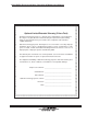
CyberChiller Series Installation, Operation & Maintenance Manual Frederick, Maryland USA 21704 CyberChiller Series Telephone: (301) 620-2033 Facsimile: (301) 620-1396 APPENDIX A - FORMS Stulz Air Technology Systems Inc. Frederick, Maryland USA 21704 Telephone: (301) 620-2033 Facsimile: (301) 620-1396 Checklist for Completed Installation ❏1 ❏2 ❏3 Proper clearances for service access have been maintained around equipment. Piping completed to refrigerant or coolant loop (if required).
CyberChiller Series Installation, Operation & Maintenance Manual NOTES (©October, 2006)
CyberChiller Series Installation, Operation & Maintenance Manual Frederick, Maryland USA 21704 CyberChiller Series Telephone: (301) 620-2033 Facsimile: (301) 620-1396 Periodic General Maintenance Checks and Services Checklist Date: ____________________________ Prepared By: ___________________________ Model Number: ____________________________ Serial Number: __________________________ Item Number: ____________________________ Monthly Miscellaneous Check Glycol or Chilled Water for Air (bleed as req
CyberChiller Series Installation, Operation & Maintenance Manual NOTES (©October, 2006)
CyberChiller Series Installation, Operation & Maintenance Manual Appendix B- Glossary Definition of Terms and Acronyms SATS - Stulz Air Technology Systems, Inc.
CyberChiller Series Installation, Operation & Maintenance Manual (©October, 2006)