VoiceBox 4 I/OP User Manual Date 10/22/2010 Revision 02 Attero Tech, LLC 1315 Directors Row, Suite 107, Ft Wayne, IN 46808 Phone 260-496-9668 • Fax 260-496-9879 www.atterotech.
VoiceBox 4 I/OP User Manual IMPORTANT SAFETY INSTRUCTIONS The symbols below are internationally accepted symbols that warn of potential hazards with electrical products. This symbol, wherever it appears, alerts you to the presence of uninsulated dangerous voltage inside the enclosure -voltage that may be sufficient to constitute a risk of shock. This symbol, wherever it appears, alerts you to important operating and maintenance instructions in the accompanying literature. Please read the manual. 1. 2. 3. 4.
VoiceBox 4 I/OP User Manual Note: This equipment has been tested and found to comply with the limits for a Class A digital device, pursuant to Part 15 of the FCC Rules and EN55022. These limits are designed to provide reasonable protection against harmful interference when the equipment is operated in a commercial environment.
VoiceBox 4 I/OP User Manual Contents 1 - Overview...............................................................................................................................................................................................................................1 1.1 – What’s in the Box?............................................................................................................................................................1 1.2 – Optional Extras ..................................
VoiceBox 4 I/OP User Manual 1 - Overview The VoiceBox 4 I/OP CobraNet Audio Interface is a full featured 4 input, 4 output mic/line preamp with an integrated CobraNet interface for sending and receiving digital audio over a CobraNet network. In addition, the VoiceBox 4 I/OP provides a dedicated DSP for compression, equalization, and gain on each input channel as well as limiting on each output channel.
VoiceBox 4 I/OP User Manual 1.
VoiceBox 4 I/OP User Manual 1.4 – Signal Processing All signal processing after the analog preamplifier circuitry is implemented in the digital domain using powerful 32-bit DSP hardware and high quality algorithms. All signal processing parameters mentioned are configurable using the Attero Tech Control Center software.
VoiceBox 4 I/OP User Manual 2– Installation Figure 3 – VoiceBox 4 I/OP Connectors and Indicators 1 Power LED 2 Power Socket – Use with optional 12 V DC wall wart only.
VoiceBox 4 I/OP User Manual Installation of the VoiceBox is very straight forward. All connections to the VoiceBox should be made before the power is applied. o o o Attach any audio sources that will be used to the inputs. The inputs are balanced so be sure to check what output type the source is in order to find how to connect it correctly (see section 2.1 – Hardware Connections). Select phantom power and/or the level of input gain required as necessary. Attach the outputs to the required audio devices.
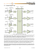
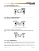
VoiceBox 4 I/OP User Manual 2.1.2 – Input from a Balanced Source To connect balanced sources to the VoiceBox 4 I/OP, connect positive output to positive input, negative output to negative input, and connect the grounds together through the cable shield. Figure 6 - Balanced Source Connection 2.1.
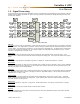
VoiceBox 4 I/OP User Manual 2.2 – Phantom Power and Gain Switches The VoiceBox has the ability to provide phantom power and input gain on each input. Switches are provided for controlling both these features independently on each input. G1 to G4 are 4 groups of switches controlling input gain on inputs 1 to 4 respectively. The remaining four switches, number 1 through 4 are the four phantom power switches for inputs 1 to 4 respectively.
VoiceBox 4 I/OP User Manual 3 – Software Installation and Setup The Attero Tech Control Center application should be used to examine and modify device configuration. This includes not only the standard CobraNet features such as audio routing but also the device specific controls of the signal processing blocks the VoiceBox uses. Refer to the Attero Tech Control Center User’s Guide for installation and setup instructions.
VoiceBox 4 I/OP User Manual 3.2 – Input Processing Figure 11 – Local Input Channel Processing for Channels 1 and 2 Figure 11 shows the general layout of the form. It contains five tabs. The first two tabs are dedicated to local input processing with two input channels on each tab. The third is dedicated to the Matrix Mixer. The final two tabs are dedicated to local output processing with two output channels on each tab.
VoiceBox 4 I/OP User Manual 3.2.1 – Input EQ The input EQ consists of several cascaded filters: a low and high cut, a low EQ, a mid sweep and a High EQ. The low cut is a 12dB / Octave filter with adjustable frequency. The high cut is a 6dB / Octave filter with adjustable frequency. The low EQ is a low shelf filter set at 400 Hz with adjustable gain. The mid sweep is a parametric EQ with a fixed bandwidth of 1 Octave but adjustable frequency and gain.
VoiceBox 4 I/OP User Manual 3.3 – Matrix Mixer The Matrix Mixer (shown in Figure 15) combines a number of controls. Each of the Local and CobraNet inputs are shown in columns with the send controls running across in rows. Figure 15 – Matrix Mixer Tab of VoiceBox Interface 3.3.1 – Matrix Mixer Input Controls Each input has its own set of controls at the bottom of the column. There is an input fader that ranges from -100 dB to 0 dB as well as “Mute”, “Invert” and “Solo” buttons.
VoiceBox 4 I/OP User Manual 3.3.3 – Matrix Mixer Output Controls Figure 16 - Matrix Mixer Output Controls: Local (left) and CobraNet (right) The output section of the Matrix Mixer is split into two tabs. The first tab shows the local outputs. The second tab shows the CobraNet outputs. The mixer sends are colored according to the corresponding output level fader. The output faders range from -100 dB to +12 dB.
VoiceBox 4 I/OP User Manual 3.4 – Output Processing The audio for the local outputs is passed from the matrix mixer to the output processing stage. Figure 18 below shows the form for outputs 1 and 2. The layout is identical for outputs 3 and 4.
VoiceBox 4 I/OP User Manual 3.4.1 – Output EQ The output EQ stage has five cascaded bands of parametric EQ followed by a high pass filter. Each parametric EQ has adjustable frequency (20 Hz to 20 kHz), bandwidth (0.1 to 3.0) and gain (-12 dB to +12 dB). Each stage has it’s own clip LED to warn if the signal at the stage is clipping or not. The high pass filter is a 12 dB / Octave filter with adjustable Frequency from 20 Hz to 20 kHz. This filter also has a clip indicator.
VoiceBox 4 I/OP User Manual 3.5 – General Controls 3.5.1 – Stereo Linking The local input channel controls have the option to be linked together to form stereo pairs. This same feature, called stereo linking, is also available for the local output channels also. Channels 1 & 2, may be linked and channels 3 & 4 may be linked. Both links may be active at one time. There is no provision for the settings in channels 3 and 4 to be linked in any way to inputs 1 & 2 and vice versa.
VoiceBox 4 I/OP User Manual 4 – Troubleshooting 4.1 – Checking the Network Connection The CobraNet network connection can be diagnosed by noting the status of the LEDs just above the Ethernet connector on the VoiceBox. These LEDs will be on, off, or flashing depending on the current state of the network connection. Below is a table showing the states of the LEDs and what device status they represent.
VoiceBox 4 I/OP User Manual 5 – ARCHITECTS & ENGINEERS SPECIFICATION The CobraNet interface unit shall provide four mic/line analog inputs on rear panel pluggable 3-pin barrier strips. Selectable gain of 0 dB, +30 dB, +50 dB, and +12 V phantom power shall be provided on rear panel DIP switches for each analog input channel. The internal analog to digital signal conversion shall be performed at 16, 20, or 24-bit resolution with a sampling frequency of 48 kHz.
VoiceBox 4 I/OP User Manual APPENDIX A – Introduction to CobraNet CobraNet is an audio networking technology for delivery and distribution of real-time, high quality, uncompressed digital audio using a standard Ethernet network. It is implemented using a combination of hardware, firmware, and the CobraNet protocol. Unlike other audio networking or distribution technologies, CobraNet is a true network and exists on standard Ethernet networks using standard Ethernet hardware.
VoiceBox 4 I/OP User Manual The modes are as follows: o Unicast – Used for one-to-one connections. In this mode, only one receiver at a time can receive this bundle. Once a link is established from this transmitted bundle to a receiver, any future requests for that bundle from other potential receivers will fail. o Multicast – Used for one-to-many connections. This mode broadcasts its contents over the entire network. There is no restriction on the number of receivers.
VoiceBox 4 I/OP User Manual APPENDIX B- Reference Documents The following table lists the relevant reference documents. Document Title Revision CobraNet Programmer’s Reference (Cirrus Logic) Attero Tech LLC 2010 v2.