
Owner's manual


VoiceBox 4 I/OP
User Manual
Attero Tech LLC 2010 Page 4 614-00008-02
2– Installation
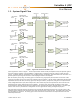
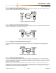
Figure 3 – VoiceBox 4 I/OP Connectors and Indicators
1 Power LED
2 Power Socket – Use with optional 12 V DC wall wart only.
3 Serial Bridge interface connector
4 CobraNet Ethernet interface connector and indicators
5 4 x Balanced audio inputs and associated mic/line and phantom power switches
6 4 x Balanced Audio outputs