
Owner manual


DialogBox 4/2
User Manual
Attero Tech LLC 2013 Page 3 614-00011-04
2.1 – Connecting Analog Audio Devices
The DialogBox 4/2 analog inputs accept balanced or unbalanced audio via 3-pin Phoenix-type screw connectors.
When interfacing audio signals to this product, use balanced connections when possible to optimize audio
performance. The following sections provide wiring guidelines if balanced connections are not available on the
equipment being interfaced to this product.
2.1.1 – Unbalanced source to balanced input
Unbalanced sources may be used with balanced inputs by using the following wiring diagrams showing how to connect
the devices together. They show both 2-wire and 3-wire connections.
2.1.2 – Balanced source to unbalanced Input
Balanced sources may be used with unbalanced inputs by using the following wiring diagrams showing how to connect
the devices together. They show both 2-wire and 3-wire connections.
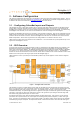
2.2 – Logic Inputs
The logic inputs are activated by pulling the input to ground. This can be done using a simple switch connected
between the input and the GND connection on the DialogBox. If electronic control is required, use a volt-free output
such as a relay output or an open collector output. Typical wire connections are show in Figure 6 below.
1 2 1 2
Figure 6 - Logic Input Connections Methods
Figure 3 - 2-wire Unbalanced Source Connection
Figure 2 - 3-wire Unbalanced Source Connection
Figure 5 – 2-wire balanced to unbalanced
Figure 4 – 3-wire balanced to unbalanced