ATTO FibreCenter™ 3400 Secure Data Path Application Installation and Operation Manual © 2002 ATTO Technology, Inc. All rights reserved. All brand or product names are trademarks of their respective holders. No part of this manual may be reproduced in any form or by any means without the express written permission of ATTO Technology, Inc.
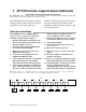
Contents 1 Fibre Channel is a key technology for storage ................................1 Glossary 2 ATTO FibreCenter supports diverse SAN needs .............................3 Quick start instructions 3 ATTO FibreCenter 3400 characteristics ............................................5 Specifications Local and network management Features 4 Setting up the FC Rack System .........................................................
7.3 Configuration commands 17 Flush Rate Reset Setup Switch Switch Delay 8 Updating firmware ..............................................................................19 Linux Kernel Update Flash File System (FFS) Update 9 Troubleshooting ..................................................................................20 Index: Command Line Interface ................................................................ i Appendix A: Standards and compliances ...........................................
1 Fibre Channel is a key technology for storage Fibre Channel is a serial communications technology designed to transfer large amounts of data between a variety of hardware systems over long distances. It is a key technology for applications that require shared, high bandwidth access to storage. Fibre Channel provides a logical point-to point serial channel for the transfer of data between a buffer at a source device and a buffer at a destination device.
Term Definition LED Light-emitting diode, a type of diode that emits light when current passes through it. Visible LEDs are used as indicator lights on all sorts of electronic devices. LUN Logical Unit Number: a Fibre Channel identifier of a device N_port A port that connects a node to a fabric or to another node as in a point-to-point configuration.
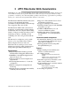
2 ATTO FibreCenter supports diverse SAN needs The ATTO FibreCenter 3400 provides a 2-gigabit Fibre Channel rackmount hub configured with eight Fibre Channel ports and an Ethernet management port. The ATTO FibreCenter 3400 integrates industryleading performance and Storage Area Network capabilities into mid-range applications. Available as a Fibre Channel rack system module, it provides dependable performance for high availability systems through hot swappable, dual power modular design.
Exhibit 2-2 Dual-zone configuration (Zone 2 and Zone 3). Each zone is independent of the other, and so may be configured to run at different or the same speed: 1 Gigabit or 2 Gigabit. Ports 2, 3 and 4 may access port 1, but only one at a time, under control of the Command Line Interface Setup and Switch commands. Ports 6, 7 and 8 may access port 5, but only one at a time under control of the Setup and Switch commands.
3 ATTO FibreCenter 3400 characteristics ATTO FibreCenter 3400 is a 2-Gigabit Fibre Channel hub configured with eight (8) Fibre Channel ports and an Ethernet management port. The FibreCenter 3400 is designed to integrate industry leading performance and Storage Area Network (SAN) capabilities into mid-range applications by providing a high-speed, central connection point for Fibre Channel connections.
Exhibit 3-1 Front view of the FibreCenter 3400 Exhibit 3-2 Module view of the FibreCenter 3400 Secure Data Path Applicationv 6
4 Setting up the FC Rack System The ATTO FC Rack System is a configurable 19-inch rack system with two bays designed to house the ATTO FibreCenter 3400. The 1U rackmount enclosure provides the flexibility to integrate the ATTO FibreCenter in pairs. The following items are included with the ATTO FC Rack System: modules. Ambient air near the inlets should not exceed 40° C. ❈Up to two (2) ATTO FibreCenter modules ❈One (1) or two (2) power modules.
+12 Volts @ 5 Amps (60 watts) continuous, 5.8 amps (70 watts) peak. Power draw: The maximum power draw is 2 Amps @ 110 Volts for the entire ATTO FC Rack System. When the ATTO FC Rack System has two power modules, the entire unit will draw 2 Amps @ 110 Volts. LED indicator The green LED indicator on the power module will light when the module is correctly installed and the switch is turned on showing that power is being drawn from this module and is available on the backplane.
5 Setting up the ATTO FibreCenter The ATTO FibreCenter 3400 fits into a standard rack mount module enclosure. While configuration changes can be made “on the fly,” data transmission will be interrupted. To make changes without impacting data, make changes before activating data transmission. Installing the FibreCenter 1 Slide the hub module horizontally into the rack enclosure until you feel it make contact with the backplane connector.
Connecting Fibre Channel ports The Fibre Channel ports connect into an Arbitrated Loop. When devices connected to the FibreCenter 3400 are powered up, each NL_Port must sign in with the other ports on the loop. Each port first attempts to find an FL_Port within the loop. When it does, it knows it is a part of a public loop connected to a fabric. If it does not, it knows it is a part of a private loop consisting of other NL_Ports only.
6 Configuring the ATTO FibreCenter The ATTO FibreCenter 3400 may be configured as one 8-port hub (Zone 1) or two 4-port hubs (Zone 2 and Zone 3). Each Fibre Channel bus in the two-zone configuration can run at different speeds (1Gb or 2Gb). The zones may be configured as either a one or two A-B style switch in a FC-AL loop. Configuration is managed through a 10/100 BaseT Ethernet port.
FibreCenter 3400 Switching Patterns A-B switch model Invalid Switching Patterns Zone P1 P2 P3 P4 P5 P6 P7 P8 Hub ports Zone P1 P2 1 ✓ ✓ 1 ✓ 1 ✓ 1 ✓ 1 ✓ 1 ✓ 1 ✓ 2 ✓ 2 ✓ 2 ✓ P3 P4 P5 P6 P7 any P8 2 ✓ ✓ ✓ must be 1-1 map ✓ ✓ P8 not in zone 2 ✓ ✓ 3 ✓ Reason: P4 not in zone 3 ✓ ✓ ✓ ✓ ✓ ✓ ✓ ✓ 3 ✓ 3 ✓ 3 ✓ ✓ ✓ ✓ Exhibit 6-1 Single zone configuration (Zone 1), an eight-port hub configuration.
7 Command Line Interface use and guidance You will be able to perform all configuration via the Telnet interface through the Ethernet port using Command Line Interface (CLI) commands. To configure the ATTO FibreCenter you will access the Command Line Interface (CLI), a set of ASCII commands, through a Telnet session.
Exhibit 7-3 Command conventions. Do not type symbols when entering commands.
7.1 Ethernet and Telnet configuration commands Configure the ATTO FibreCenter 3400 using a Telnet session over the Ethernet port. The commands in this section configure or provide information about the Ethernet port and the Telnet session. Default Router Sets a new default router address for the Telnet server. Set the default router within the subnet as defined by the subnet mask and IP Address. Limit: 0-255 Default: 0.0.0.0 Action: set•RACK •000•Default•Router•[n.n.n.
7.2 Diagnostic commands The commands in this section only provide information about the ATTO FibreCenter 3400. Access this information using these command line interface commands in a Telnet session over the Ethernet port. Status Displays the status of the power supplies and the cooling fans.
7.3 Configuration commands Configure the ATTO FibreCenter 3400 using a Telnet session over the Ethernet port. The commands in this section configure or provide information about the ATTO FibreCenter 3400. Flush, Setup and Switch commands are all closely related. Flush Undoes all previous Setup commands since the most recent Flush or Switch command Actions: Flush•000 Information: none Rate Sets (fixes) the data rate for each zone in the FibreCenter 3400.
Exhibit 7.
8 Updating firmware The Linux Kernel and the Flash File System may be updated by accessing the FibreCenter 3400 through an Ethernet network. in the usual manner OR at the bash# prompt, type reboot and hit Enter. Linux Kernel Update 1 Attach the FibreCenter 3400 to an Ethernet network. 2 Configure the FibreCenter for Ethernet access. 3 Start up a Telnet session on the host to the IP address of the FibreCenter 3400 and login as root.
9 Troubleshooting The fault LED indicates that a signal is being received, but the signal contains enough faults to make the port fail and go into bypass mode. Port LEDs on the ATTO FibreCenter are generally lighted if the port is enabled through the Setup CLI command and an active device is connected to the port. However, if you want to test your configurations without having active devices attached to the ports, enter the command Switch- Forcemode while in the command line interface.
Index: Command Line Interface A summary of the Command Line Interface commands, their defaults, an example of how they might be used, and where you can find the specifics of the command. Commands which have no default values associated with them have a blank entry in that column of the table. Command Default Example Default Router 0.0.0.0 set•RACK •000•Default•Router•0.1.0.
Appendix A Standards and compliances The ATTO Technology FibreCenter 3400 described in this manual generates and uses radio frequency energy. If this equipment is not used in strict accordance with the manufacturer's instruction, it can and may cause interference with radio and television reception. See the Technical Specification sheet for a full list of certifications.
Appendix B Contact ATTO Technology, Inc. Customer service, sales information and technical support are available by phone Monday through Friday, Eastern Standard Time 8:00 a.m. to 8:00 p.m., or by fax and web site 24-hours a day. ATTO Technology, Inc. 155 CrossPoint Parkway Amherst, New York 14068 (716) 691-1999 • voice (716) 691-9353 • fax http://www.attotech.com ATTO Technology can also be reached via e-mail at the following addresses: sls@attotech.com Sales Support: Technical Support: techsupp@attotech.