Diamond Storage Array VT-Class Installation and Operation Manual © 2005 ATTO Technology Inc. All rights reserved. All brand or product names are trademarks of their respective holders. No part of this manual may be reproduced in any form or by any means without the express written permission of ATTO Technology Inc. 2/05 6.
Contents Preface 1.0 Diamond Storage Array-VT Product Overview .............................1 Diamond-VT features Fibre Channel model SCSI model 2.0 Diamond-VT Technical Overview ...................................................3 ADXT Powers ATA to New Levels 3.0 Installation Instructions ..................................................................
.0 ATTO ExpressNAV: Browser-based Interface ..............................23 Browser compatibility Opening an ExpressNAV session Navigating ExpressNAV 5.1 ExpressNAV Pages ...............................................................25 Status Ethernet SNMP Serial Port Fibre Channel Storage Management RAID Clear Data Logical Units Partitions Zoning Tape Volumes Tape Drives Move Medium Rebuild Configuration Advanced Restart Help 6.0 CLI: Interface via ASCII-based Commands ................................
.4 Fibre Channel Configuration Commands ...........................35 FcConnMode FcDataRate FcFairArb FcFrameLength FcFullDuplex FcHard FcHardAddress FcNodeName FcPortInfo FcPortList FcPortName FcScsiBusyStatus FcWWName 6.5 Serial Port Configuration Commands .................................37 SerialPortBaudRate SerialPortEcho SerialPortHandshake SerialPortStopBits 6.6 Maintenance Services Commands ......................................
Temperature VirtualDriveInfo ZoneInfo ZoneState 6.8 Drive Management Commands ............................................
7.0 Configuring the Diamond-VT ..........................................................47 RAID Level 10 RAID Level 5 Virtual Tape Volumes Hot Spare sleds Zones Interleave Enhancing performance 7.1 Virtual Tape ............................................................................49 Configuration examples 7.2 Optional Hot Spare Sled .......................................................50 7.3 Zones ......................................................................................
Appendix A Glossary .............................................................................i Fibre Channel technology SAN technology SCSI protocol Appendix B ATA Disk Technology .......................................................iii Appendix C Information Command Returns .......................................iv Driveinfo VirtualDriveInfo Appendix D Sample Zoning Command Sequences ............................
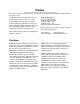
Preface This guide will take the technology-savvy user through the installation and maintenance of the Diamond Storage Array-VT. The Diamond-VT was designed to meet your need for large amounts of easily accessible storage using proprietary Aggregated Data Transfer Technology (ADXTJ) to merge the power of multiple, high performance ATA disk drives with the sustained data transfer rates required by sophisticated computer users. Your comments help us improve and update our products.
1.0 Diamond Storage Array-VT Product Overview The Diamond Storage Array-VT Class offers up to 30 Virtual Tape drives and up to 60 virtual tapes in a rack mount or floor model configuration. The Diamond-VT appears and functions to ISV (Independent Software Vender) applications as if it were a traditional tape device although it is actually an array of ATA disk drives.
• Aggregated Data Transfer Technology (ADXTJ) for high performance/scalability • Ultra ATA 100 megahertz (Mhz) • RAID Level 10 and RAID Level 5 configurable • Zoning capability compatible with third party servers, switches and with deliverables from industry standards organizations.
2.0 Diamond-VT Technical Overview The Diamond-VT uses Aggregated Data Transfer Technology (ADXT) to achieve the high data transfer performance you need. ADXT merges the performance of multiple ATA drives together to achieve sustained, full bandwidth Fibre Channel data transfer rates.
ADXT Powers ATA to New Levels The original notion of RAID was to build high capacity, reliable storage subsystems using large numbers of inexpensive disk drives. Thus its original definition: Redundant Array of Inexpensive Drives. Over time that definition became Redundant Array of Independent Drives and the inherent cost advantage in a RAID system was lost.
3.0 Installation Instructions If you are familiar with the Diamond-VT, Fibre Channel, SCSI and RAID configurations, you may set up and configure the Diamond-VT using these instructions. Find details, illustrations and other guidance for more involved operations and special cases in the rest of this manual. CAUTION Before configuring the Diamond-VT, ensure that any computer data to be stored on the array is properly backed up and verified.
6 Follow the screens to find information about the array or to configure the array from the factorydefault settings. The Diamond-VT may be set up in a RAID Level 5 or RAID Level 10 configuration with or without Hot Spare sleds and/or set up in a zoned configuration. If the Diamond-VT is not attached to a DHCP server and you wish to change the defaults 1 At the Ready prompt after POST (see above), type set IPAddress [desired IP address].
3.1 Diamond-VT Components The Diamond-VT has been designed to be easy to use, maintain and upgrade. It features a durable steel outer case and modular components in either a floor or a rack mount model. Immediately upon receipt, check the shipping carton for damage from mishandling. Contact us at once via the means that is easiest for you (see Warranty on page A-xv) if the carton has been mishandled or displays any signs of damage.
Rack mount model The system management card is at the left front of the case. Intelligent midplane (internal) At its center is a DB-9 serial System Management Card RS-232 port which allows a connection for setup, monitoring and upgrade of the unit from any computer system with an RS-232 interface. The optional 10/100 BaseT Ethernet management services card enables Telnetbased monitoring and Disk drive sleds (12) management. It also provides the ability to update the firmware in the array via FTP.
3.2 Diamond-VT Physical Setup The Diamond-VT is shipped completely assembled with two 120 VAC power cords for use in the United States and Canada. Spaced rail pairs in some rackmount cabinets. Immediately upon receipt, check the shipping You can mount the Diamond-VT using two sets of carton for damage from mishandling. Contact us rail pairs spaced to accommodate the overall at once by the means easiest for you (see Warranty length of the unit (approximately 23 inches).
General Instructions 1 Insert the proper connector into the Host Interface Card in the back of the Diamond-VT. (See Connecting a Fibre Channel Array on page 11 or Connecting a SCSI Array on page 13). 2 Connect the cable (Fibre Channel or SCSI) from your host system to the Host Interface Card connector on the back of the DiamondVT. The cable you use depends upon your application, the environment and distance.
3.2.1 Connecting a Fibre Channel Array The Diamond-VT supports up to two Fibre Channel Host Interface Cards (HIC). Physical connections and CLI commands contribute to the Fibre Channel topology. The Diamond-VT may have two Fibre Channel Host Interface Cards (HIC). Each HIC is connected by a Fibre 2 Gb HIC uses Channel cable via an SFP 2 SFPs to connect up to 2 FC cables (small form factor pluggable) module into a point-to-point or loop Fibre Channel topology.
Exhibit 3.2.1-2 Possible 2 gigabit Fibre Channel physical connections depending on which Fibre Channel connection mode has been selected.
3.2.2 Connecting a SCSI Array The SCSI Diamond-VT uses a VHDCI connector and SCSI cables to connect to a host. It automatically detects the type of Host Interface Card it is using without any intervention. or connect a cable between the second connector and the next device on the SCSI bus. To connect the SCSI Diamond-VT 1 2 Insert a SCSI VHDCI connector into the Host Interface Card in the back of the Diamond-VT.
14 SCSI connections
4.0 Accessing the Diamond-VT Communicate with the Diamond-VT through the Fibre Channel link, the RS-232 port or the Ethernet port using Command Line Interface commands or ATTO ExpressNAV, an integrated user management console. You may configure and tune the Diamond-VT for different environments and applications, update the firmware, monitor internal power and temperature status, report on hardware diagnostics and log failures.
SNMP SNMP, or Simple Network Management Protocol, is an application layer protocol that allows network devices to exchange management information. Through a combination of standard and custom MIBs (Management Information Base), the Diamond-VT provides status and error indications to an SNMP server, allowing the Exhibit 4.0-1 Array to be managed with other devices in a complex system through a common interface. You use CLI commands to configure up to six unique Trap addresses.
4.1 In-band CLI Over Fibre Channel In-band Command Line Interface (CLI) configures and manages the Diamond-VT using SCSI-based CLI commands over a Fibre Channel port connection. 3 A subsequent Write Buffer command In-band CLI allows a programmer to configure executes the new command line and overwrites the Diamond-VT while it is moving data. Using a the previous results in the buffer with new programmer’s interface, CLI commands as results.
to an initiator that specifies an incorrect Buffer ID, Mode, Length or Buffer Offset. The Mode is Exhibit 4.1-2 always Data (0x2), the Buffer ID is always 0 and the Buffer Offset is always 0. The SCSI command process: reserve the Diamond-VT, send the command, release the Diamond-VT.
4.2 Serial Port Access The Diamond-VT provides remote service operations over the RS-232 serial port using standard terminal emulation software available with most systems. The Diamond-VT supports service operations over the RS-232 serial port using standard terminal emulation software available with most systems. • 8 bit ASCII 1 • flow control none Connect a DB-9 null modem serial cable between the port marked RS-232 on the front of the Diamond-VT and one of the computer’s serial ports.
20 Serial port access
4.3 Ethernet Access: Telnet and SNMP Protocols The optional 10/100 BaseT Ethernet port provides Telnet- or SNMP-based monitoring and management. The 10/100 Base T Ethernet management services card provides Telnet-based monitoring and management, including firmware update using FTP. Remote system monitoring is also available using Simple Network Management Protocol (SNMP). An agent resides in the Diamond-VT which takes information from the Array and translates it into a form compatible with SNMP.
8 Call technical support (see Warranty in the Appendix, page xv) to get the appropriate MIB file for your Diamond-VT. 14 The SNMP management software contacts the agent in the Diamond-VT. The screen displays system information. 9 For each client, copy the MIB file to the directory containing the SNMP management software. 15 Status is monitored and reported through the SNMP management software. 10 From within the SNMP management software, compile the file attodmnd-mib.
5.0 ATTO ExpressNAV: Browser-based Interface The easiest way to communicate with the Diamond Storage Array is to use ATTO ExpressNAV, a user-friendly GUI interface accessed through a browser to control the most common capabilities of the array. Access ATTO ExpressNAV from any browser that supports the latest standards for XHTML 1.0 and CSS1. To take full advantage of the ExpressNAV interface you should have Java script enabled through your browser. Minimum requirement is for Internet Explorer 5.
Exhibit 5.
5.1 ExpressNAV Pages Each page in the ATTO ExpressNAV interface provides information and/or configuration parameters based on specific topics. Each page can be reached through the menu on the left hand side of each page.
Logical Units Displays information on the logical units which have been configured and allows you to change the status from online or offline or degraded. • • • • Minimum operating temperature Maximum operating temperature Identify Diamond Restore defaults Partitions Refer to Maintenance Services Commands on page 38 for details.
6.0 CLI: Interface via ASCII-based Commands The command line interface (CLI) provides access to Diamond-VT services through a set of ASCIIbased commands. CLI commands may be entered while in CLI mode or by accessing the Advanced CLI Configuration page in the ExpressNAV interface. • CLI commands are context sensitive and generally follow a standard format: SaveConfiguration command or by using a separate FirmwareRestart command.
Exhibit 6.
6.1 Summary of CLI Commands A summary of the Command Line Interface commands, their defaults, an example of how they might be used, and where you can find the specifics of the command. Commands which have no default values associated with them have a blank entry in that column of the table.
Command IdeWriteCache Defaults enabled Example Page set idewritecache disabled 42 Info Info 39 InquiryData InquiryData 11456 124345 1.0 11242 14564 2 42 IPAddress 10.0.0.1 set ipaddress 19.172.2.2 33 IPDHCP Disabled set ipdhcp enabled 33 IPGateway 0.0.0.0 get ipgateway 33 IPSubnetMask 255.255.255.
Command Defaults Example Page SystemSN get systemsn 32 TapeDriveInfo TapeDriveInfo 40 set TapeVolumeBlockSize 2 44 TapeVolumeInfo 40 TapeVolumeBlockSize 1 TapeVolumeInfo TapeWriteProtect Disabled set TapeWriteProtect enabled 44 TelnetPassword diamond set TelnetPassword 123ABC 33 TelnetTimeout Disabled set TelnetTimeout 360 34 TelnetUsername telnet set TelnetUsername diamond1 34 get Temperature 40 get VerboseMode 32 VirtualDriveInfo virtualdriveinfo active 40 Zmodem zm
6.2 General Use Commands The following commands, listed alphabetically, describe or perform general functions. FirmwareRestart Causes a warm restart of the Diamond Storage Array. before the restart and saved will be implemented. Restart or no Restart parameter is optional Immediate: FirmwareRestart Immediate: SaveConfiguration Help Displays a list of available commands. Type ‘help’ followed by a command name to display detailed command-specific information.
6.3 Ethernet Commands Ethernet configuration commands configure the Ethernet and TCP/IP parameters for the Diamond Storage Array with an optional Ethernet management services card. EthernetSpeed Specifies the speed of the Ethernet Network to which the Diamond Storage Array is connected.
SNMPTraps Enables or disables SNMP traps. Default: disabled Set syntax: set SNMPTraps [enabled|disabled] Requires a SaveConfiguration Restart command Get syntax: get SNMPTraps SNMPUpdates Enables or disables the SNMP Management Information Base (MIB) database.
6.4 Fibre Channel Configuration Commands The Fibre Channel ports are configured with default settings but may be customized to your specifications using the CLI commands in this section. FcConnMode Specifies the Fibre Channel topology for the Diamond Storage Array. Options are loop only (loop), point-topoint only (ptp), loop preferred (loop-ptp) or point-topoint preferred (ptp-loop). See Connecting a Fibre Channel Array on page 11 for more information on Fibre Channel topology.
FcPortList Lists the status of all available Fibre Channel ports. Immediate command: FcPortList FcPortName Returns the Fibre Channel port name stored in NVRAM for this Fibre Channel port. Get syntax: get FcPortName [port number] FcScsiBusyStatus Specifies the SCSI status value returned when the Diamond is unable to accept a SCSI command because of a temporary lack of resources. FcWWName Sets or view the Word Wide Name (WWPN) of the referenced Fibre Channel port.
6.5 Serial Port Configuration Commands The serial port configuration may be customized by using the following commands: SerialPortBaudRate Sets the baud rate the Diamond Storage Array uses for its terminal interface. Choices are 2400, 9600, 19200, 38400, 57600, 115200. SerialPortHandshake Describes which handshaking method the Diamond Storage Array uses for its terminal interface (hardware, Xon/Xoff or none).
6.6 Maintenance Services Commands Maintenance commands allow updating and maintenance of the Diamond-VT. FcScsiBusyStatus You may set the Diamond to report busy or queue full when it is unable to accept a command. SaveConfiguration command and a system restart. If required, the return Ready. * will be displayed after the FirmwareRestart Causes a warm restart of the Diamond Storage Array return for the modification.
6.7 Diagnostic Commands Diagnostic commands provide information or diagnostic tools for Fibre Channel, SCSI and Serial port configurations, Diamond Storage Array settings and the status of various commands which affect the ATA drives. AudibleAlarm Enables or disables the audible alarm in the Diamond Storage Array. When enabled, an alarm sounds when the Fault LED on the front panel blinks.
PowerAudibleAlarm Silences the audible alarm for a current power supply failure. The alarm will be activated on the next power failure. SledFaultLED Changes the state of the selected sled LED to the indicated state. Choose the sled number, 1-12, or all, turn on or off Immediate command: PowerAudibleAlarm disabled Default: off RAID5ClearDataStatus Displays the status of RAID5 Clear Data processing. S represents the sled number, D represents the drive number.
6.8 Drive Management Commands The Diamond Storage Array ATA drives may be monitored or configured through the CLI using the commands listed below. ATADiskState Sets the ATA disk to the specified state. Enter the sled number (1-12), drive number (1-2) and online or offline CAUTION In a Hot Spare configuration, a drive sled should only be taken offline if there is absolutely no activity on that drive. If there is any activity, the rebuild of the Hot Spare sled may be flawed.
DriveWipe Initializes a drive: wipes it of all data. Drive must be offline Set syntax: DriveWipe [Destination Sled] [Dest Drive] Requires a SaveConfiguration Restart command Get syntax: DriveCopyStatus ECC Specifies or displays whether ECC is enabled or not. If ECC is not available, an ECC invalid message will be returned.
software. The remaining four characters will be entered by the system automatically to identify the tape number. See Virtual Tape on page 49 and Optional Hot Spare Sled on page 50 for more information and examples. Note The maximum number of tape volumes and tape drives for RAID Level 5 is 30. The maximum number of tape volumes and tape drives for RAID Level 10 is 15.
RebuildPriority Sets the priority of a RAID Level 5 or 10 rebuild. If you select High priority, rebuild I/O requests are implemented before system I/O requests. I f you select Low priority, rebuild I/O requests executes only when there are no pending I/O requests. If you select Same priority, rebuild I/O and system I/O receive equal consideration.
ZoneClearAll Removes all entries from the Planned Zone Configuration.Removes any active zones if followed immediately by a ZoneCommit command. command must be entered as enabled to activate the zone before using the ZoneCommit command (which makes the Planned Zone Configuration the Active configuration). Set syntax: ZoneClearAll Set syntax: ZoneRemoveDevice [zone_name] [device_LUN...] ZoneCommit Commits the current Planned Zone Configuration, making it the persistent, Active configuration.
46 CLI: configure drives
7.0 Configuring the Diamond-VT The Diamond-VT can be configured as RAID Level 10 or RAID Level 5 with zones and/or Hot Spare sleds. Partitions are created automatically during configuration of Virtual Tape emulation. The default is a single zone which includes all LUNs (devices), all ports and all hosts. RAID is a storage configuration which uses multiple disk drives to increase capacity, performance and/or reliability.
Advanced CLI configuration page of the ExpressNAV interface. Zoning supports security by granting or denying access between initiators and devices as defined by an administrator. A zone is a collection of devices which can access each other. The devices in a zone usually include one or more initiators, one or more devices, and one or more paths between the initiators and the devices. Interleave The interleave size sets the amount of data to be written to each drive in a RAID group.
7.1 Virtual Tape When the Diamond-VT is configured as a Virtual Tape, it is divided into several tape volumes based on your choice and the RAID level you choose. Virtual Tape provides increased performance by reducing the time needed to backup and restore data. Virtual Tape volumes reside on Virtual Drives. The Diamond-VT appears to hosts as a tape library, allowing ISV packages to issue a set of tape library commands to perform backup and restore operations to the Diamond-VT.
7.2 Optional Hot Spare Sled To maintain array up time with minimal risk of data loss, individual sleds which fail may be replaced with a spare sled. In most configurations, if a member of a virtual device becomes degraded, you must swap out the faulted sled as defined in Hot Swap Operating Instructions on page 69. If you have not enabled AutoRebuild, you must also start a manual rebuild. However, Hot Spare sleds may be designated as replacements for faulted sleds without intervention by you or a host.
7.3 Zones Zoning is a collection of related Diamond-VT capabilities supporting flexible Diamond configuration management configurable via CLI commands in the Command Line Interface mode or in the Advanced CLI Configuration page in the ExpressNAV interface. Zoning supports security by granting or denying access between initiators and devices as defined by an administrator. A zone is a collection of devices which can access each other.
the Active configuration will be copied into the Planned configuration. To determine what is in the Planned configuration, type ZoneInfo Planned. Active configuration is persistent and establishes the Diamond zoning configuration after powerup. The Planned configuration becomes the Active configuration after successful execution of the ZoneCommit command. The Active configuration is replicated as the Planned configuration after the successful ZoneCommit, after power-up and after ZoneRetrieve.
Configuring Zoning CAUTION Be careful when changing Diamond-VT zoning configurations. Internal validation logic cannot detect misconfigurations An unrestricted zone configuration, exactly mimicking the LUN configuration, is created internally after the first power-up or restart after installation of the Diamond-VT. No special operating modes are required and Zoning can be easily installed with no impact on previous configurations.
Errors The Zone commands manage entries in the Zone definition tables which manage the overall zoning process. Definition tables are indexed by unique keys (zone_name). All definition tables are repositories for their respective data and participate in establishing the configuration by executing the ZoneCommit command. The integrity of these tables is essential to the data integrity of the Diamond-VT. If the Zone definitions are faulty problems can occur.
8.0 Updating Firmware Engineers, technicians and/or system administrators/integrators may update the firmware of the Diamond-VT using the Command Line Interface (CLI) (See Accessing the Diamond-VT on page 15) via the RS-232 serial port or the optional Ethernet management services card. Updating firmware via the RS-232 serial port To update the firmware via a connection to the RS-232 serial port, you will need 5 In the Send File box, enter the current Diamond flash (“...”.
3 The Diamond should acknowledge receiving the file and display a message not to interrupt power for 90 seconds. Copy the latest Diamond-VT image file (“...”.ima) onto the host computer and note its directory c:\diamond\flash\“...”.ima 4 CAUTION Change directories to the place where you copied the “...”.ima file Do not interrupt the flash process. If the process is interrupted, the Diamond-VT will become inoperable and will have to be returned to the factory for repair.
9.0 Diagnostics, Upgrade and Maintenance The Diamond-VT provides a number of visual, audible and computer system-generated indicators to identify the operational status of the array. System status and error information is readily available. Various methods are available to correct problems or to upgrade equipment and firmware. RS-232 Monitoring Port and CLI One tool to support a Diamond-VT is a host computer with an RS-232 port and terminal emulation software.
midplane temperature were to reach a higher point, the temperature warming alarm will report Critical, the Array will be taken off line, and all disk drive activity will be disabled. When the ambient temperature decreases to within standard operating range, the drives will be powered back on and the host will be allowed to access the data. temperature warning alarm will report OK during normal operating conditions.
an error code, please provide both the first and second blink code values. During a fault condition, more detailed information about the fault may be available via the CLI or the ExpressNAV interface over the RS232 interface port or the optional Ethernet port. These error messages should be reported to technical personnel to assist in debugging the problem.
60 Monitoring, reporting
9.1 Troubleshooting The Diamond-VT provides a number of indicators to identify the operational status of the array. System status and error information is readily available. If your situation is not defined here or elsewhere in the manual, if these solutions do not help, or if you have any questions or concerns about any aspect of operating the Diamond-VT, contact technical support.
• Follow the instructions in the appropriate chapters of this manual to remove, replace and reconfigure the drive such as Hot Swap Operating Instructions on page 69. • You may copy drives by using Command Line interface commands. Refer to Drive Management Commands on page 41. If a power supply fails • Verify the power cord is correctly plugged and there is power at the power receptacle. • If there is power, the cord is secure and the blower and power supply LEDs are off, replace the blower unit.
9.2 Resetting Defaults Resetting the Diamond-VT to defaults will not alter the RAID configuration, zoning configuration, IP configuration or Telnet information. However, resetting the Diamond-VT to factory defaults is a last-ditch effort to recover from corrupt configurations or complete failure. All data will be lost, but the zoning configuration will remain. CAUTION Data will be lost if you follow these procedures. Make sure you have no other choice before resetting the Diamond-VT to factory defaults.
Exhibit 9.2-2 Configurations which will be changed during a RestoreConfiguration command Reset if default chosen Reset during factorydefault Command Default ▼ AudibleAlarm Disabled AutoRebuild Disabled DiamondName “............” EthernetSpeed Auto FcConnMode Loop FcDataRate Auto FcFairArb Enabled FcFrameLength 2048 FcFullDuplex Enabled FcHard Disabled FcHardAddress 0x03 IdentifyDiamond Disabled IdeTransferRate 4 IPAddress 10.0.0.1 IPDHCP Disabled IPGateway 0.0.0.
9.3 Rebuilding RAID Level 5 and 10 Configurations If a sled must be removed and a new sled inserted into the Diamond Storage Array while it is configured in a RAID Level 5 or 10, you must rebuild the RAID Level using CLI commands or the ExpressNAV interface. WARNING Selecting RAID parameters causes all previous drive data on the Diamond Storage Array to be erased. Make sure all of your information is backed up before setting up RAID groups.
To synchronize mirrored drives manually The most efficient method to synchronize Virtual Tape configurations is to enable Hot Spares or the auto rebuild feature. 1 2 3 Connect to Diamond Storage Array services via the RS-232 port or the optional Ethernet management services card (see Accessing the Diamond-VT on page 15). You should now be in CLI. Access the RAID page of the ExpressNAV interface (see ATTO ExpressNAV: Browser-based Interface on page 23).
10.0 Hardware Maintenance The disk drive sleds, blower assemblies, power supplies, host interface cards, and system management card may be replaced with identical or upgraded parts. CAUTION Do not leave empty openings on the front or rear of the Diamond-VT under any circumstances. Empty openings affect airflow and may cause the unit to overheat and shut down.
Exhibit 10-2: Above, disk drive sled partially pulled out of the Diamond Storage Array. Bottom left, top of disk drive sled. Bottom right, underside of disk drive sled showing individual drives Exhibit10-3: The Fibre Channel or SCSI Host Interface Card may be replaced by shutting power down, removing any cable attached to the port, removing the GBIC or SFP according to manufacturer's instructions, loosening the screws at the top and bottom of the card, then carefully pulling out the unit.
10.1 Hot Swap Operating Instructions To maintain array up time, individual disk drive sled assemblies, power supplies and blower assemblies can be replaced with the unit fully operational. Special instructions need to be followed to perform these operations. Disk Drives 4 CAUTION • Individual disk drive sled assemblies may be replaced while the array is operating with no other intervention only if there is absolutely no activity on that drive.
Power Supplies removal of a power supply and change the LED on the system management board. The CLI will issue messages about the change (see Diagnostics, Upgrade and Maintenance on page 57). CAUTION Do not leave empty openings on the front or rear of the Diamond-VT under any circumstances. Empty openings affect airflow and may cause the unit to overheat and shut down. Blower Assemblies CAUTION WARNING Do not leave empty openings on the front or rear of the Diamond-VT under any circumstances.
Appendix A Glossary The following terms are only a few examples of the language used for Fibre Channel, SCSI and storage systems. For more information, visit the websites of these professional organizations: the Fibre Channel Industry Association www.fibrechannel.org; the Fibre Channel Consortium www.iol.unh.edu/consortiums/index.html click on Fibre Channel; the Storage Area Networking Industry Association www.snia.org, or SCSI Trade Association www.scsita.org.
Term Definition F_port A port in the FC fabric where a N_port may attach FC-AL Fibre Channel Arbitrated Loop: an FC network in which up to 126 systems and devices are connected in a loop topology, with each transmitter connecting to the receiver of the device to its logical right; multiple FC-AL loops can be connected via a fabric switch FL-port A port in the FC fabric where a NL_port may attach in an arbitrated loop firmware Software stored in read-only memory (ROM) or programmable ROM; easier to
Appendix B ATA Disk Technology ATA is the dominant disk drive technology today and will be for the foreseeable future. It offers all the cost advantages of a mass produced, consumer-driven technology which is rapidly being driven forward. Today ATA also offers all the performance and reliability features needed to create high performance ATA-based disk storage arrays. ATA disk drives are used in the enormous PC marketplace and an estimated 85% of all disk drives sold today contain an ATA interface.
Appendix C Information Command Returns Driveinfo Sled Capacity Errors TYPE ...VDID === ====== ..
Read 00000000 00000000 Write 00000000 00000000 Errors 00000000 LunInfo for a JBOD setup LUN TYPE State === ==== ===== 0 Processor ONLINE 1 JBOD ONLINE 2 JBOD ONLINE 3 JBOD ONLINE 4 JBOD ONLINE 5 JBOD ONLINE 6 JBOD ONLINE 7 JBOD ONLINE 8 JBOD ONLINE 9 JBOD ONLINE 10 JBOD ONLINE 11 JBOD ONLINE 12 JBOD ONLINE 13 JBOD ONLINE 14 JBOD ONLINE 15 JBOD ONLINE 16 JBOD ONLINE 17 JBOD ONLINE 18 JBOD ONLINE 19 JBOD ONLINE 20 JBOD ONLINE 21 JBOD ONLINE 22 JBOD ONLINE 23 JBOD ONLINE 24 JBOD ONLINE Capacity Errors SerialN
Write 00000000 00000000 Errors 00000000 LunInfo for a RAID5 1 configuration LUN TYPE State Capacity === ==== ===== ====== 0 Processor ONLINE 0MB 1 RAID5 ONLINE 1612749MB Errors SerialNumber ==== ============ 0 0 V80EE4YC5AM0000 LunInfo 1 RAID5 SerialNumber V80EE4YC5AM0000 Virtual Drive ID 59, Capacity: 1612749 MB (0x000c4de6f00 blocks) Operations Blocks Read 00000000 00000000 Write 00000000 00000000 Errors 00000000 LunInfo for a RAID5 4 configuration LUN TYPE State Capacity Errors SerialNumber === ==== ==
Volume Partition Total % Capacity Write ID LUN VDID ID Capacity Used Protection =============================================== 059 - 59 0 3439315MB 0% disabled Ready. TapeVolumeInfo 059 Volume ID : 059 LUN : VDID : 59 Partition ID :0 Device Kind : RAID5 Device State : OFFLINE Total Capacity : 3439315MB % Capacity Used : 0% Write Protection : disabled Primary Volume ID : G80FQC2E____________5AA0000 Volume Sequence Number : 0 VirtualDriveInfo TYPE VDID #Parts State Capacity ....
A-viii
Appendix D Sample Zoning Command Sequences First time configuration (after download) QuickRAID under Zoning “first time” configuration, an all/all/all configuration in the selected QuickRAID configuration. All zone commands except ZoneClearAll Clears any previously-defined zones ZoneCommit Sets the new zoning configuration. ZoneCommit affect only the planned configuration. ZoneCommit sets the Planned Configuration into the Active Configuration. Simple configuration 2 hosts.
Asymmetric Model 3 hosts, 1 metadata controller (also a host), RAID 5 with 3 LUNs. All zone commands except ZoneCommit affect only the planned configuration. ZoneCommit sets the Planned Configuration into the Active Configuration.
Combined Symmetric/Asymmetric Model Many hosts. All zone commands except ZoneCommit affect only the planned configuration. ZoneCommit sets the Planned Configuration into the Active Configuration.
Appendix E Specifications Environmental and physical • Depth: 585mm (23.03”) • Humidity: 10-85% non-condensing • Approximately 39 kg (86 pounds) fully loaded with 24 drives • Normal operating temperature at sea level: 540o C Floor Mount Dimensions • Storage temperature: -25-60o C • Height: 524mm (20.62”) 3U • AC input voltage 100-240V rated • Width: 137mm (5.39”) • 50/60 Hz • Depth: 595mm (23.
Appendix F Product Safety Safe handling of the Diamond-VT will help protect its components as well as the people working with them. • The Diamond-VT is heavy (92 pounds for the floor model, 86 pounds for the rack mount system). Two people will be needed to move it safely. • Mechanical, shock and energy hazards are present through the system if one or more of the modules is removed.
Appendix G Part numbers Each Diamond-VT has a master part number to identify it. The floor model base number is on the side of the unit. The rack mount part number is on the top of the unit and near the host interface cards.
Appendix H Warranty Manufacturer limited warranty Manufacturer warrants to the original purchaser of this product that it will be free from defects in material and workmanship as described in the ATTO Technology website, www.attotech.com. Manufacturer liability shall be limited to replacing or repairing, at its option, any defective product. There will be no charge for parts or labor should Manufacturer determine that this product is defective.