ATTO FastStream Storage Controller Installation and Operation Manual FastStream SC 5300 Fibre Channel to SCSI SAN Storage Appliance FastStream SC 5500 Fibre Channel to SAS/SATA SAN Storage Appliance FastStream SC 5700 Fibre Channel to Fibre Channel SAN Storage Appliance
ATTO Technology, Inc. 155 CrossPoint Parkway Amherst, New York 14068 USA www.attotech.com Tel Fax (716) 691-1999 (716) 691-9353 Sales support: sls@attotech.com Technical support: Monday -- Friday, 8am-8pm EST techsupp@attotech.com © 2008 ATTO Technology, Inc. All rights reserved. All brand or product names are trademarks of their respective holders. No part of this manual may be reproduced in any form or by any means without the express written permission of ATTO Technology, Inc.
Contents 1.0 ATTO FastStream Offers Data Protection ...................................................1 FastStream 5000 Series features RAID protection features Audio/video features Additional FastStream 5300 features Additional FastStream 5500 features Additional FastStream 5700 features 1.1 FastStream SC 5300 Physical Attributes ..........................................3 Dimensions Cooling and airflow Power Fibre Channel ports SCSI ports Management ports LED indicators 1.
.0 Configure Storage into RAID Groups ...........................................................13 Features you may choose Auto-Rebuild Fault Tolerance Initialization Selecting an application Preliminary steps Quick Digital Video Audio General Digital Video, General IT or Database Creating a custom setup 5.0 Modify System Values ...................................................................................
8.0 Manage ATTO Devices, Configurations .......................................................37 Creating a unique name for your FastStream Discovering, managing other ATTO devices Saving or restoring a configuration 9.0 Interface Options ...........................................................................................39 Using the ExpressNAV Storage Manager Using the serial port Using Telnet 10.0 Update Firmware ...................................................................................
1.0 ATTO FastStream Offers Data Protection The ATTO FastStream™ Storage Controller is an ideal solution for the cost sensitive demands of today’s networked storage environments, offering great performance, OS independence, simplified management, and RAID protection for all of your critical data. Adding RAID ensures your data is protected without compromising performance.
Additional FastStream 5500 features Additional FastStream 5700 features • • • • • • • 2 independent 4-Gb Fibre Channel Host Interfaces backward compatible with 2-Gb and 1-Gb FC operation 2 3-Gb miniSAS device interfaces provide 8 lanes of SAS/SATA connectivity supporting initiator mode for any combination of up to 64 SAS and SATA devices SES (SCSI Enclosure Services) support 2 4-Gigabit Fibre Channel host interfaces 2 4-Gigabit Fibre Channel device interfaces Supports up to 32 disk drives SES (SCSI E
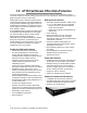
1.1 FastStream SC 5300 Physical Attributes The ATTO FastStream SC 5300 is a Fibre Channel to SCSI storage appliance which can be seamlessly integrated into a new or an existing storage environment. The ATTO FastStream SC 5300 is available in a desktop model and in an industry-standard 1U form factor for easy integration into racks. For installation instructions, refer to Install the FastStream Storage Controller on page 9. Dimensions Width: 17 inches Length: 8.94 inches Height: 1.
SCSI ports: A green LED on each port indicates activity if is lit. LEDs on the faceplate are: A bicolor Ready/Fault LED is lighted green to indicate ready, lighted yellow to show a faulted condition, and off indicates not ready. Exhibit 1.1-1 SCSI ports: A green LED on each port indicates activity if is lit. Fibre Channel ports: bicolor LED indicates FC speed. If it is off, speed is 1-Gb; if it is green, 2-Gb, and yellow indicates 4-Gb FC.
1.2 FastStream SC 5500 Physical Attributes The ATTO FastStream SC 5500 is a Fibre Channel to SAS/SATA SAN storage appliance which can be seamlessly integrated into a new or an existing storage environment. The ATTO FastStream SC 5500 is available in a desktop model, an industry-standard 1U form factor for easy integration into racks and as an embeddable board-level product. For installation instructions for the desktop and 1U form factor models, refer to Install the FastStream Storage Controller on page 9.
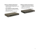
Ethernet port connector: a lighted green LED shows a valid link; off indicates that no link is present, and blinking indicates activity. A separate bicolor LED indicates 10/100/1000 MbE speed: green on indicates 100 MbE; yellow on indicates 1000 MbE, and off indicates 10 MbE Fibre Channel port: a lighted green LED indicates link; off means no link. A separate green LED indicates FC speed; lit means 4-Gb/sec; off means 1- or 2Gb/sec.
1.3 FastStream SC 5700 Physical Attributes The ATTO FastStream SC 5700 is a Fibre Channel to Fibre Channel storage appliance which can be seamlessly integrated into a new or an existing storage environment. The ATTO FastStream SC 5700 is available in an industry-standard 1U form factor for easy integration into industry-standard racks. For installation instructions, refer to Install the FastStream Storage Controller on page 9. Dimensions Width: 17 inches Length: 8.94 inches Height: 1.
LEDs on the front are: A green power LED A bicolor Ready/Fault LED: lighted green to indicate ready, lighted yellow to show a faulted condition, and off indicates not ready. Fibre Channel ports: bicolor LED indicates FC speed. If it is off, speed is 1-Gb; if it is green, 2-Gb, and yellow indicates 4-Gb FC. A separate green LED indicates activity if it is lit, no activity if it is off. Exhibit 1.3-1 The connector side of the FastStream 5700 Exhibit 1.3-2 Detail of the connector side of the FastStream.
2.0 Install the FastStream Storage Controller If you have not already completed the instructions on the Quick Start page packed with your FastStream, use the following instructions to install the FastStream. Unpacking the packing box; verifying contents • • • • • • The FastStream.
Select Internet Options. In the Internet Options screen, select the Security tab. 4 Click on the Trusted Sites icon. 5 Click on the Sites button. 6 In the text box Add this Web site to the zone, add the IP address of the appliance. You may use wild cards. 7 Click on Add. 8 Uncheck the Require server verification check box. 9 Click OK. 10 At the bottom of the Internet Options box, click on OK and close the box.
3.0 Ensure Drive Integrity The ATTO FastStream initialize and verify drive feature discovers and re-maps bad sectors on drives providing reliable media for your RAID groups. Before creating any RAID group you should initialize and verify the drives selected to be in the RAID group to ensure drive integrity. When selected, the FastStream writes a pattern to the entire drive, verifying the drive’s readiness and reliability.
After creating RAID groups 1 2 3 If you are not already in the ExpressNAV Storage Manager, type the IP address of your appliance in a standard browser. On the splash screen, click Enter Here. In the box provided, type in your user name and password, and click OK. Click on the Diagnostics button on the left hand side of the ExpressNAV Storage Manager. Choose either Initialize and Verify Drives or Read-Only Drive Test from the Select User Process menu.
4.0 Configure Storage into RAID Groups The ATTO FastStream allows configuration of storage into DVRAID, JBOD, RAID Level 0, 1, 1+0, 4 or 5 for the FastStream SC 5300 and 5700, plus RAID Level 6 for the FastStream SC 5500, with the ability to create multiple partitions. RAID is a storage configuration which uses multiple drives to increase capacity, performance and/or reliability.
• • • If no unallocated drive is available, you must replace the faulted drive and a rebuild begins. If you are using a FastStream 5300, you must initiate a system scan using the CLI command BlockDevScan to discover the drive before the rebuild can take place; all other appliances automatically discover the additional drive. Hot Spares are not required, allowing the maximum number of drives for data storage.
Quick Digital Video 1 2 3 4 5 6 7 8 9 After choosing Quick Digital Video, the Setup Wizard page appears. Select your operating system. If you chose Windows, click Yes, the system restarts. After the restart completes, continue to Step 3. If you chose Mac, continue on to Step 3. If all your drives do not appear in the Find Drives box, click on System Scan. For the FastStream 5300, this setup requires exactly 6, 12 or 24 drives appear as available on the screen after the scan.
Creating a custom setup • If the application setups do not suit your needs, you may use Custom Setup to configure the FastStream. 1 After choosing Custom Setup button, the RAID Setup Wizard page appears. Click on Next. 2 Decide if all drives are to be available to both ports. • If you select Yes, the same node name is assigned to both ports. • If you select No, different node names are assigned to each FC port. • The choice you make establishes the access for all RAID groups attached to this FastStream.
• 512 bytes is the default size for most operating systems. • For Windows XP (32-bit support) select 4 KB sectors to enable large volume support (greater than 2 TB). 15 Select a SpeedRead option. SpeedRead looks ahead during reads and stores the data in cache memory.The optimum setting depends on your actual I/O and storage. You may adjust this setting later. • Enabling SpeedRead may boost performance when you are running video playback and other applications which access data sequentially.
18
5.0 Modify System Values Default values are appropriate for most configurations, but may be modified for your needs using ATTO ExpressNAV Storage Manager. It is best practice to change the default user name and password to a user name and password important to you. Other configurations may also be changed, however, use extreme caution when changing default values.
6 Make any changes. • Appliance name: The appliance name is a unique 8-character identifier which is displayed at the top of each screen. You may find this useful if you are managing multiple ATTO devices from a single workstation. Refer to Manage ATTO Devices, Configurations on page 37. • Time and date: use a remote time server to set the time and time zone, or manually set the time and date. Refer to Date, Time, TimeZone and SNTP in Appendix A, CLI Provides an ASCII-based Interface.
6.0 Monitor Storage, Configurations You may determine the performance of drives attached to the FastStream using various displays and tests in ExpressNAV Storage Manager. The following instructions assume you have already set up at least one RAID group. The ATTO FastStream collects various metrics to measure performance for physical drives attached to the FastStream during normal system operation and drive initialization and verification.
Configuration Display page Clicking on Details from the Health and Status Monitor page gives you added information about various aspects of the FastStream and attached storage. Click on the arrow next to the group you wish to view.
6.1 Phone Home: Email Alerts Phone home Email notification allows the FastStream to send an Email message to you, a network administrator or other users when certain events occur with the FastStream. Serious error messages are sent immediately, while messages for less serious errors are sent every 15 minutes.
Exhibit 6.1-1 The Error Notification page.
6.2 Drive Diagnostics You may determine the performance of drives attached to the FastStream using various displays and tests in ExpressNAV Storage Manager. The following instructions assume you have already set up at least one RAID group. The ATTO FastStream collects various metrics to measure performance for physical drives attached to the FastStream during normal system operation and drive initialization and verification.
Drive performance and health Another way to determine your drives’ status is to follow the Preliminary instructions, above, and click on the Drive Performance and Health menu item. 1 Follow the instructions in Preliminary steps above. 2 Click on the Drive Performance and Health menu item. 3 The Drive Performance and Health page appears. • Click on Show Help Text and Drives for an alternative view of the test progress.
6.3 SCSI Enclosure Services (SES) Drive enclosures may provide a SCSI Enclosure Processor which indicates enclosure health status, drive identification and drive fault. The ATTO Storage Controller recognizes drive enclosures that provide SCSI Enclosure Services (SES) information. You may use SES to identify individual drives, all the drives in the same enclosure, all the drives in a single RAID group, or faulted drives. You may also select drives and monitor the status of the enclosure.
Identifying SES elements The SES Monitor page found by clicking on Details in the Enclosure Status section of the Health and Status Monitor page shows SES information about specific enclosures (see Exhibit 6.3-4). If you would like information about specific drives of the RAID groups or enclosures of which they are members, use the Identify SES Elements page. 1 If you are not already in the ExpressNAV Storage Manager, type the IP address of your appliance in a standard browser.
Monitoring SES elements Enclosures which provide SES information are listed in the Enclosure Status section of the Health and Status Monitor (see Exhibit 3) and through the Enclosure Services arrow on the Manage menu. 2 Use the Health and Status Monitor 1 If you are not already in the ExpressNAV Storage Manager, type the IP address of your appliance in a standard browser. On the splash 3 screen, click Enter Here. In the box provided, type in your user name and password, and click OK.
Use the Manage menu 1 2 If you are not already in the ExpressNAV Storage Manager, type the IP address of your appliance in a standard browser. On the splash screen, click Enter Here. In the box provided, type in your user name and password, and click OK. The Health and Status Monitor page appears. Click on the Manage menu item on the left hand side of the screen. 3 4 5 6 In the Select User Process box, click on the Enclosure Services arrow. Select the Monitor Enclosure Services button. Click Next.
7.0 Modify Storage Use the ExpressNAV Storage Manager to replace a failed drive, add new drives or redesign RAID configurations. You may modify various aspects of storage using the Manage Menu found by clicking on the tab on the left hand side of the ExpressNAV Storage Manager. Be cautious when deleting storage or rearranging storage configurations because data could be compromised or lost.
If you want to continue click Yes. The configuration completes and the Health and Status Monitor page appears. 3 4 If you wish to start over, click No. 5 CAUTION Adding drives to a RAID group If you have unallocated drives, you can increase the number of drives used by an existing RAID group by adding an unallocated drive to the group. The drives is configured into a separate partition in the RAID group. You may have to add more than one drive depending on the RAID group setup.
Modifying RAID group mapping You may change the LUNs of drives manually or let the ExpressNAV Storage Manager map drives for you. 1 Follow the instructions in Preliminary steps on page 31 and click on the RAID Groups arrow from the Select User Process box. 2 Click on the Modify RAID Group Mapping button. 3 Click on Next. 4 Select the RAID group you wish to change from the drop down box. 5 Select the method you wish to use to map the partitions. Refer to Modifying RAID group partitions below.
Modifying RAID options You may change Auto-Rebuild and SpeedRead configurations. Refer to Step 14 and Step 17 under Creating a custom setup on page 16 for details on these features. 1 Follow the instructions in Preliminary steps on page 31 and click on the RAID Groups arrow from the Select User Process box. 2 Click on the Modify RAID Options button. 3 Click on Next. 4 5 6 7 8 Select the RAID group from the drop down box. Select the options you wish to change. Click on Commit. A warning box appears.
Removing RAID configuration data If you move single drives between devices without erasing the drives, you may want to clean stale RAID configuration data from the drives, permanently removing the drive from the RAID group. Drives must belong to a RAID group now or have once belonged to a RAID group and are labeled Replaced after system scans. 3 Click in the Clean RAID Configuration data radio button from the Select User Process box. 4 5 Click Next.
36
8.0 Manage ATTO Devices, Configurations You may save the current configuration of your FastStream SC, use a configuration from another FastStream, or change the configurations of other ATTO devices from your current browser using the ExpressNAV Storage Manager.
Saving or restoring a configuration You may save the configuration of the FastStream you are currently using, restore the configuration from a previously-saved configuration for that FastStream, or clone a configuration from another ATTO FastStream using the Save/Restore feature. 3 4 5 CAUTION Note It is best practice to save a copy of your configuration settings to a file to easily replace a unit or to set up additional controllers.
9.0 Interface Options The best way to manage, monitor and configure the FastStream is to use the ExpressNAV Storage Manager, a browser-based application included with your FastStream, but you may use a terminal emulation program or Telnet. Using the ExpressNAV Storage Manager Use the ExpressNAV Storage Manager to manage, monitor and configure the unit. The choices you make lead you from screen to screen. Choices which are not available are greyed out.
Using the serial port To connect to a terminal emulation program to manage the FastStream, use the serial port. 1 Connect a cable from FastStream RS-232 serial port or header to the serial (COM) port on a personal computer. 2 Start a terminal emulation program on the personal computer, and use it to connect to the FastStream. For example, if you are using Hyper Terminal on a computer running a Windows operating system: a. Type FastStream in the New Connection dialog box. b. Click OK. c.
10.0 Update Firmware Firmware updates are available on the ATTO website. Contact your ATTO sales representative for complete information. The ATTO FastStream has several processors which control the flow of data. The firmware to control these processors can be upgraded in the field using the ExpressNAV Storage Manager. Be sure all data is backed up before updating firmware to prevent data loss. 5 The Diagnostics Menu page appears. From the Select User Process box, select Update the Firmware.
42
Appendix A CLI Provides an ASCII-based Interface The command line interface (CLI) uses ASCII commands typed while in CLI mode. • CAUTION Do not use CLI unless you are directed to by an ATTO technician. Changing parameters may cause loss of data and/or disruption to performance and reliability of the FastStream. • • • The ExpressNAV Storage Manager is the preferred method to operate and manage the FastStream. Refer to Using the ExpressNAV Storage Manager on page 39 for details.
Symbol/Abbreviation GroupName MemberIndex mp1 PartitionIndex Indicates The name of the RAID group, designated by the user, to which a block device is assigned. Use RGDisplay to discover RAID group names Index designation of a RAID group member as found by using the RMStatus command Ethernet port used to manage the FastStream Index designation of a partition as found by using the PartitionDisplay command CLI error messages The following error messages may be returned by the Command line Interface: ERROR.
Command Default BridgeModel BridgeName Example get bridgemodel ““ set bridgename Omega6 ClearEventLog cleareventlog Date set date 03/03/2003 DefaultInterleave 128 set defaultinterleave 64 DeleteAllMaps deleteallmaps DisplayEventLog displayeventlog DisplayEventLogFilter all all all set displayeventlogfilter gen info all DriveTest drivetest begin DriveTestConfig set drivetestconfig read DriveTestList set drivetestlist all DriveTestStatus get driveteststatus DumpConfiguration dumpc
Command Default HSRemove IdentifyBridge Example hsremove 3 disabled Info set identifyBridge enabled info IPAddress 10.0.0.1 get ipaddress mp1 IPDHCP enabled set ipdhcp mp1 disabled IPDNSServer IPGateway IPSubnetMask set ipdnsserver mp1 172.15.12.123 0.0.0.0 255.255.0.
Command Default Example RGErase rgerase g1 RGHaltConversion rghaltconversion g1 RGHaltErase rghalterase g1 RGHaltInitialization rghaltinitialization g1 RGHaltRebuild rghaltrebuild g1 RGMemberAdd rgmemberadd g1 22 RGMemberRemove rgmemberremove g1 22 RGPreFetch 0 rgprefetch g1 2 RGRebuild rgrebuild g1 RGResumeConversion rgresumeconversion g1 RGResumeErase rgresumeerase g1 RGResumeInitialization rgresumeinitialization g1 RGResumeRebuild rgresumerebuild g1 RGSectorSize 512 RGSpan
Command Default Example SESDiskFailureAlarm (SC 5500, 5700) disabled set sesdiskfailurealarm enabled SESEnclosures (SC 5500, 5700) sesenclosures SESIdentify (SC 5500, 5700) set sesidentify RAID g1 SESIdentifyStop (SC 5500, 5700) sesidentifystop all SESMute (SC 5500, 5700) mute SESPoll (SC 5500, 5700) 60 set sespoll 20 SESStartingSlot (SC 5500, 5700) 1 set sesstartingslot 2 SESStatus (SC 5500, 5700) sesstatus SNTP enabled SNTPServer sesmute remind 192.43.244.
BlockDevClean ClearEventLog Removes any RAID configuration data from the block device with the specified block ID. Clears the contents of the EventLog. No new entries are recorded until the operation is completed. CAUTION All RAID group setup information is lost and you lose all RAID group data. BlockDevClean [BlockDevID] BlockDevIdentify Lights the LED of a disk drive. Use either RAID GroupName and MemberIndex, or block ID.
DriveTest EmailNotify Starts or stops a drive test with the previously-specified configuration and drive list. Drives which are in-use by the test are not available for RAID configuration or RAID operations. Only one test can be run at a time. Regulates Email notification. DriveTest [Begin | Cancel] DriveTestConfig Configures the next drive test to perform: initialize (destructive write-only), read (non-destructive read-only), verify (destructive verify), or init-verify (destructive write-read-verify).
EthernetSpeed Regulates the speed of the unit’s Ethernet port(s). If Auto is enabled, the Ethernet speed is negotiated. When hard set, 10 and 100 speeds are half duplex. Default: auto set EthernetSpeed [mp1] [10 | 100 | auto] SaveConfiguration Restart command required get EthernetSpeed [mp1] EventLog Regulates event logging. When enabled, the unit records various system events to the event log.
FCPortList IdentifyBridge Displays a list of available FC ports and their current status. Valid reported status values are Up, Down, Failed, Reserved and Disabled. If you enable this command, the Fault LED on this unit blinks so that hardware may be identified. Disabling this option cancels the blinking.. FCPortList Default: disabled set IdentifyBridge [enabled | disabled] get IdentifyBridge FCSCSIBusyStatus SC 5300 Choose to report busy or queue full when the unit is unable to accept a SCSI command.
IPSubnetMask PartitionDisplay Controls the current subnet masks used by any Ethernet port(s) on the unit. If IPDHCP is enabled, the get command reports the current IP subnet mask assigned by the network DHCP server. Lists all the partitions available in the specified RAID group. The partitions are listed in order of contiguousness (as opposed to index order). Default: 255.255.0.0 set IPSubnetMask [mp1] [xxx.xxx.xxx.
PassThroughRediscover ReadOnlyPassword SC 5500, 5700 Specifies a password which allows only read and no writes. It is case sensitive, 0 to 32 characters, and cannot contain spaces. An empty password can be configured by not specifying one. Makes any previously-deleted pass through target devices visible to the host. PassThroughRediscover Password Specifies the password used for all sessions. Password is case sensitive, 0 to 32 characters, and cannot contain spaces.
RGAutoRebuild RGDiskWriteCache Uses drives assigned as Hot Spares, then available drives, as automatic replacements for any member that fails. If enabled, produces higher write performance with a small risk of data loss after a system failure. If disabled, drives are updated at the expense of some write performance.
RGPreFetch RGResumeRebuild Specifies the prefetch value for all RAID groups or for the specified RAID Group. SC 5500 Default: 0 set RGPreFetch [GroupName | all] [1-6] get RGPreFetch [GroupName | all] Continues the rebuild(s) on the specified existing RAID group. If no MemberIndex is specified, all stopped rebuilds on that RAID group are continued. For RAID 6 groups, if a MemberIndex is specified, all halted RAID members on the span with that MemberIndex resume as well.
RMStatus RouteDisplay Displays the status of all RAID members within the specified RAID group or a particular RAID member if specified within the specified RAID group. Displays a combined list of host protocol address to target destination device mappings. RMStatus [GroupName] Route SC 5300 Assigns a host protocol address to a target destination device. More than one FC LUN may be assigned to a partition.
SCSIPortList SCSITargets SC 5300 SC 5300 Lists the status of all available SCSI ports. Lists the physical devices that are connected and running on the specified SCSI port. SCSIPortList SCSIPortReset SCSITargets [sb] SC 5300 SerialNumber Resets the specified SCSI bus. Displays the serial number of the unit. The serial number is a 13 character field. The first seven alphanumeric characters are an abbreviation representing the product name.
SESDiskFailureAlarm Note The command SESEnclosures must be executed before executing SESMute. SC 5500, SC 5700 Activates an audible alarm when the appliance determines that a RAID member disk drive has failed. The enclosure which contains the failed disk drive creates the sound, other enclosures are unaffected. Default: disabled set SESDiskFailureAlarm [enabled | disabled] get SESDiskFailureAlarm SESEnclosures SC 5500, SC 5700 List SES-enabled enclosures which have been discovered by the appliance.
TailEventLog VerboseMode Displays new events to the terminal. Type quit then press ENTER to exit tail mode. Controls the level of detail in CLI Help output and command response output for the current CLI session. TailEventLog Temperature Default: enabled set VerboseMode [enabled | disabled] get VerboseMode Displays the current internal operating temperature of this unit in degrees Celsius.
Appendix B Design RAID Groups The ATTO FastStream provides instant hardware data protection and intelligence to existing storage independent of the storage type. CAUTION Note If a drive has corrupt or outdated configuration data, that drive cannot be assigned to any RAID group. Ensure all drives are configured properly. Refer to Ensure Drive Integrity on page 11 or Removing RAID configuration data on page 35.
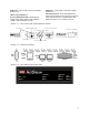
RAID Level 0: striping, no redundancy other. RAID Level 0 provides no data protection. If one drive fails, all data within that stripe set is lost. RAID Level 0 is used by applications requiring high performance for non-critical data. The ATTO FastStream supports 2 to 16 drives per RAID Level 0 group.
RAID Level 1+0: striping, mirror spans two drives RAID Level 1+0 increases data transfer rates while ensuring security by writing the exact same data simultaneously to two or more different drives. Stripe 1 Stripe 2 Stripe 3 RAID Level 1+0 is used in applications requiring high performance and redundancy, combining the attributes of RAID Levels 1 and 0. The ATTO FastStream supports an even number of 4 to 16 drives per RAID Level 1+0 group.
RAID Level 6: striping, two parity blocks distributed among drives RAID Level 6 increases reliability for mission critical applications by striping both data and dual parity across multiple drives, writing data and parity blocks across all the drives in a RAID group. RAID 6 provides can tolerate failure of two drives and provides redundancy during rebuilds. The ATTO FastStream requires at least four drives to build a RAID 6 group.
Appendix C SCSI Cabling Additional information to physically connect ports to devices and to your SAN. SCSI cables and devices must be chosen to maximize performance and minimize the electrical noise from the high-speed data transfers available with the SCSI protocol. Cabling and termination methods become important considerations for proper performance. SCSI cables and devices are subject to specific length and number limitations to deal with electrical problems that arise at increased operating speeds.
Exhibit A-2 Various types of SCSI operate at different speeds and require different bus lengths to support a certain number of devices. STA terms Bus speed MB/sec. max. Bus width bits Max. bus lengths in meters Singleended Differential Max. device support LVD Fast SCSI 10 8 3 25 NA 8 Fast/WIDE SCSI 20 16 3 25 NA 16 UltraSCSI 20 8 1.5 25 NA 8 Ultra/WIDE SCSI 40 16 NA 25 NA 16 Ultra/WIDE SCSI 40 16 1.
Appendix D Standards and Compliances The equipment described in this manual generates and uses radio frequency energy. If this equipment is not used in strict accordance with the manufacturer's instruction, it can cause interference with radio and television reception. See the ATTO FastStream Technical Specification sheet for your particular model for a full list of certifications for that model.
Appendix E Warranty Manufacturer limited warranty Manufacturer warrants to the original purchaser of this product that it is free from defects in material and workmanship as described in the ATTO Technology website, www.attotech.com. Manufacturer liability shall be limited to replacing or repairing, at its option, any defective product. There is no charge for parts or labor should Manufacturer determine that this product is defective.