
Specifications


7
ATTO Technology ExpressPCI UL4D and UL4S Installation and Operation Manualv
3.1 Cabling and termination
Cables and devices must be chosen to maximize performance and minimize the electrical noise from the
high-speed data transfers available with the SCSI protocol. Cabling and termination methods become
important considerations.
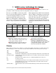
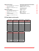
The following table lists the maximum number of
devices you may connect at specific cable
distances using differential and single-ended
SCSI in various SCSI environments.
Exhibit 3.1-1 The development of SCSI capabilities
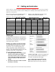
Cable types
Use high quality Ultra320-rated, well-insulated
SCSI cables to ensure error free communications.
The illustration at right depicts several internal
and external cable connectors.
Setting up cables and terminaton
The ExpressPCI Ultra320 SCSI host adapter
supports two types of SCSI signaling: Low
Voltage Differential (LVD) and Single-Ended.
Devices on the same SCSI bus must use the same
signaling, either LVD or Single-Ended.
To set up cabling and termination:
1 Determine whether you are using a single
channel or dual channel host adapter
model. One external connector indicates a
single channel host adapter; two external
connectors indicate a dual channel host
adapter.
2 Determine if SCSI devices will be installed
internally or externally.
Total bus cable length,
varies by host adapter and
type of attached devices. Refer to Exhibit 3.1-1
for details on maximum cable length.
If you combine Wide 16-bit and Narrow 8-bit
devices on the same connector,
connect the
Wide devices first (closest to the connector).
STA terms
Bus speed
MB/sec. max.
Bus width
bits
Max. bus lengths, meters Max. device
support
Single-ended LVD HVD
SCSI-1 5 8 6 - 25 8
Fast SCSI 10 8 3 - 25 8
Fast Wide SCSI 20 16 3 - 25 16
Wide Ultra/WIDE SCSI 40 16 - - 25 16
Wide Ultra/WIDE SCSI 40 16 1.5 - - 8
Wide Ultra/WIDE SCSI 40 16 3 - - 4
Ultra2 SCSI 80 16 - 12 - 16
Ultra3 SCSI 160 16 - 12 - 16
Ultra320 SCSI 320 16 - 12 - 16