
Manual

ABYC H2/IS0 9097 MARINE BLOWER PERFORMANCE SPECIFICATIONS
ATTWOOD BILGE BLOWERS LIMITED WARRANTY:
ATTWOOD CORPORATION, 1016 North Monroe, Lowell, Michigan 49331, (‘Attwood’)
warrants to the original consumer purchaser that this Attwood Bilge Blowers, numbers
1731 and 1747 will be free from defects in materials and workmanship under normal
use and service for a period of three (3) years. These models are not intended for use
in applications which allow direct contact with water or other liquids. Evidence of such
product damage voids this warranty. Attwood also warrants the Attwood Bilge Blowers,
numbers 1733 and 1749 will be free from defects in materials and workmanship under
normal use and service for a period of three (3) years from the date of original consumer
purchase. This warranty does not extend to any batteries or fuses used with the blower.
This limited warranty is not applicable if the bilge blower has been damaged by accident,
improper installation, unreasonable use, lack of proper maintenance, unauthorized repairs
or modifi cations, or other causes not arising out of defects in materials or workmanship.
Attwood’s obligations under this warranty are limited to repair of the product at Attwood’s
plant or replacement of the product at Attwood’s option and at Attwood’s expense. Any
expenses involved in the removal, reinstallation, or transportation of the product are not
covered by this warranty. The
product must be returned to Attwood’s plant at the address indicated above postage
prepaid, with proof of original purchase including date. If Attwood is unable to replace the
bilge blower and repair is not commercially practicable or cannot be timely made, or if the
original consumer purchaser is willing to accept a refund in lieu of repair or replacement,
Attwood may refund the purchase price, less an amount for depreciation. The acceptance
by Attwood of any product returned or any refund provided by Attwood shall not be deemed
an admission that the product is defective or in violation of any warranty.
THIS WARRANTY IS ATTWOOD’S ONLY EXPRESS WARRANTY OF THIS PRODUCT.
NO IMPLIED WARRANTY SHALL EXTEND BEYOND THREE (3) YEARS FROM THE
DATE OF ORIGINAL CONSUMER PURCHASE. ATTWOOD SHALL NOT BE LIABLE
FOR ANY DAMAGES FOR LOSS OF USE OF THIS PRODUCT, NOR FOR ANY OTHER
INCIDENTAL OR CONSEQUENTIAL DAMAGES, COSTS OR EXPENSES.
Some states do not allow limitations on how long an implied warranty lasts or the exclusion
or limitation of incidental or consequential damages, so the above limitations and
exclusions may not apply to you. This warranty gives you specifi c legal rights and you may
have other rights which may vary from state to state.
1.5
1.0
0.5
0 15010050 0 15010050
2.5-8,500
3.0-9,500
3.5-10,500
1.5
1.0
0.5
2.5-8,500
3.0-9,500
3.5-10,500
1.5
0.5
0
150
250
0-6,800
1.0
2.0
2.5
3.0
1.5
0.5
1.0
2.0
10050 200
0
150
250
10050 200
2.0-7,5002.5
1.0-7,150
0-6,800
2.0-8,600
1.0-7,700
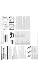
TURBO IN-LINE BILGE BLOWERS
INSTALLATION INSTRUCTIONS 09/01 69465 Rev. A
SAVE THESE INSTRUCTIONS
Model No.
Specifi cation
Voltage
CFM
Open Flow
CFM
In System
Amp
Draw
Fuse
Size
Turbo 3000 13.6 145 100 3.1 4-amp
Turbo 4000 13.6 230 125 2.9 5-amp
Turbo 4000 (24V) 27.2 230 125 2.0 3-amp
*In system = 3 ft. of duct with one 90° bend, a collector box and louvered vent on
discharge side of blower.
Blower models 1733, 1734, 1743, 1749 and 1751 (24V, 4") are water resistant. Models
1731, 1741 and 1747 are not water-resistant. All Turbo blowers are ignition protected.
Connect to 12-volt D.C. systems only (24 volt for Model 1751).
WARNING:
To prevent personal injury, always disconnect electrical connection when
installing or servicing this product.
Always use a fuse with amperage rating specifi ed for the blower model.
Before starting engines, operate blower a minimum of four minutes, then check
engine compartment for fume odor. Operate blowers when motoring below 5 miles
per hour.
Do not operate in area of high heat over 160° F (71°C).
Do not operate while refueling.
MOUNTING INSTRUCTIONS
Select a fl at mounting surface high above the bilge, clear of moisture from spray 1. or
deck wash.
Position blower with the fl ow arrow pointing toward exhaust vent. Also, mount 2. blower
at an angle to prevent moisture build-up. See Figure 1.
Mark mounting holes. Drill holes for #10 screws and secure unit in place using 3.
stainless steel screws. Do not over tighten screws.
Twist duct hose over exhaust and intake openings on blower. Ensure the retainer 4.
tabs engage corrugated rings of hose.
Install tie strap or hose clamp on the hose. Position the strap or clamp around 5. blower
housing, beyond the tabs. Tighten the strap. Do not overtighten straps or clamps.
Route intake end of hose directly to the lowest point in the bilge, with as few bends 6.
as possible. The hose pick-up must not be low enough to become submerged in
bilge water. See Figure 1.
Route exhaust end of hose directly to vent or vent collector box, with as few bends 7.
as possible. Connect hose securely to vent. See Figure 1.
Figure 1
Figure 1 Abbildung 1
Vertical Transom MountA.
Horizontal Transom MountB.
Deck MountC.
A. Senkrechte Montage am Heckspiegel
B. Horizontale Montage am Heckspiegel
C. Montage an Deck
Figure 1 Figur 1
A. Montage de tableau vertical
B. Montage de tableau horizontal
C. Montage sur le pont
A. vertikalt akterspegelfäste
B. horisontellt akterspegelfäste
C. däcksfäste
Figura 1
A. Montaje de bovedilla vertical
B. Montaje de bovedilla horizontal
C. Montaje de la cubierta
WIRING INSTRUCTIONS
Fuse holder must be installed within 72” (183cm) of the battery (+) terminal. See 1. table
for proper fuse size. Connect ON/OFF switch into the circuit and mount it in the dash
control panel.
If your boat is not equipped with a blower “WARNING” label like the one shown 2. below,
please contact our customer service department for a free label — Part No. 9158WR.
Figure 2
Figure 2 Abbildung 2
Flow ArrowA.
Bilge BlowerB.
YellowC.
BlackD.
Wire Connectors If RequiredE.
SwitchF.
FuseG.
72” (183 cm) maxH.
Battery I.
Durchfl usspfeilA.
BilgenlüfterB.
GelbC.
SchwarzD.
Drahtverbinder, falls erforderlichE.
SchalterF.
SicherungG.
Maximal 183 cm (72 Zoll)H.
AkkuI.
Figure 2 Figur 2
Flèche de débitA.
Ventilateur de caleB.
JauneC.
NoirD.
Connecteurs de fi l si requisE.
InterrupteurF.
FusibleG.
183 cm maximumH.
BatterieI.
strömningspilA.
slagvattensfl äktB.
gulC.
svartD.
kabelkontakter vid behovE.
strömbrytareF.
säkringG.
maximalt 72 tum (183 cm)H.
batteriI.
Figura 2
Flecha de fl ujoA.
Soplador de sentinaB.
AmarilloC.
NegroD.
Conectores del cable si se requierenE.
InterruptorF.
FusibleG.
1,8 m como máx.H.
BateríaI.
© 2009 Attwood Corporation
1016 N. Monroe Street, Lowell, MI 49331-0260 www.attwoodmarine.com
ABC
A
B
C
D
E
G
H
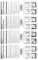
3" Blowers (1731 & 1733)
Performance at 12 VDC
4" Blowers
(1741, 1743, 1747 & 1749)
Performance at 12 VDC
3" Blowers (1731 & 1733)
Performance at 13.6 VDC
4” Blowers
(1741, 1743, 1747 & 1749)
Performance at 13.6 VDC
I
WARNING
GASOLINE VAPORS CAN EXPLODE
BEFORE STARTING ENGINE:
OPERATE BLOWER FOR 4 MINUTES
CHECK ENGINE COMP'T FOR GAS OR VAPORS
RUN BLOWER WHEN BELOW CRUISING SPEED
STATIC PRESSURE (IN-H20)
AIR FLOW (CFM)
AIR FLOW (CFM)
Flow
Flow
Flow
Flow
Speed
Speed
Speed
Speed
AMPS
AMPS
AMPS
AMPS
AIR FLOW (CFM)
AIR FLOW (CFM)
STATIC PRESSURE (IN-H20)
STATIC PRESSURE (IN-H20)STATIC PRESSURE (IN-H20)
AMPS (DC)
SPEED (RPM)SPEED (RPM)
SPEED (RPM)
SPEED (RPM)
AMPS (DC)
AMPS (DC)
AMPS (DC)