Quick Guide 4/8/16 Channel HD Analog DVR (Digital Video Recorder) Please read this manual thoroughly before use and keep it handy for future reference.
WARNING TO REDUCE THE RISK OF FIRE OR ELECTRIC SHOCK, DO NOT EXPOSE THIS PRODUCT TO RAIN OR MOISTURE. DO NOT INSERT ANY METALLIC OBJECT THROUGH THE VENTILATION GRILLS OR OTHER OPENNINGS ON THE EQUIPMENT. CAUTION CAUTION RISK OF ELECTRIC SHOCK DO NOT OPEN WARNING: TO REDUCE THE RISK OF ELECTRIC SHOCK, DO NOT REMOVE COVER (OR BACK). NO USER-SERVICABLE PARTS INSIDE.
FCC COMPLIANCE STATEMENT This device complies with Part 15 of the FCC Rules. Operation is subject to the following two conditions: (1) this device may not cause harmful interference, and (2) this device must accept any interference received, including interference that may cause undesired operation. FCC INFORMATION: This equipment has been tested and found to comply with the limits for a Class A digital device, pursuant to Part 15 of the FCC Rules.
IMPORTANT SAFETY INSTRUCTIONS 1. 2. 3. 4. 5. 6. 7. 8. 9. 10. 11. 12. 13. 14. 15. 16. 17. Read these instructions. Keep these instructions. Heed all warnings. Follow all instructions. Do not use this apparatus near water. Clean only with dry cloth. Do not block any ventilation openings. Install in accordance with the manufacturer’s instructions. Do not install near any heat sources such as radiators, heat registers, stoves, or other apparatus (including amplifiers) that produce heat.
1. Overview 1.1 Package Contents The device package contents consist of the following: Note Please check all components involved. No 1.2 Name No Name 1 DVR 5 SATA cable 2 DC Power Adapter & Power cord 6 SATA power cable 3 Mouse 7 HDD fixing screw 4 Quick guide 8 Program CD DVR Description Each part is listed in the below: 2 1 3 4 No. Name Function 1 Power status LED Pointing out device on/off. 2 Recording status LED Pointing out recording in process.
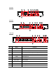
4ch DVR 1 2 4 5 6 7 8 9 A UDI O I N 3 1 4 AU DIO OU T 2 V IDE O IN VGA HD Output ALARM IN OUT 1 2 3 4 G 1 A+ B- LAN DC 12V 10 8ch DVR 1 2 3 4 5 3 4 6 7 8 9 10 16ch DVR 1 2 5 6 10 No. Name Function 1 Audio In Camera audio input port. 2 Video In Camera video input port. 3 CVBS CVBS output port (depending on device types). 4 VGA VGA output port. 5 HDMI HDMI output port. 6 LAN Network connector. 7 Alarm In/Out 8 RS485 RS-485 communication connector.
2. Installation This chapter describes the way to install DVR. When installing a device, connect rear of the device with each port on the basis of below connection map. The device starts first like below sequences: 1 Installing HDD. 2 Connecting with an exterior device. 3 Starting a system. 4 Setting a quick setup. 2.1 Installing HDD How to install HDD in the device: Withdraw the mains plug before installing HDD to reduce the risk of injury or Attention electrical shock, or device malfunction.
2.2 Starting System Power supply begins with system operation as follows: 1 Switching on initialize with below icons in order. Note Installing new HDD might take more initialize time. 2 With buzzer sounds, the start screen is presented. 3 In Log in screen, enter the ID, Password and press OK. Default ID & Password is admin/admin. Note Click to see the MAC address. If lost password, inform the MAC address to supplier to create temporary password.
Note Default ID/Password is admin/admin. The default password must be changed for security. Max character length is 12. A password can be used if it satisfies two or more in the following criteria: 1) It contains at least one lowercase English character. 2) It contains at least one uppercase English character. 3) It contains at least one special character. The special characters are “! @ # $ % ^ & * ( ) - + ...” 4) It contains at least one digit.
2.3.4 WAN Port: Select whether to use static IP or dynamic IP. IP Address, Subnet Mask, Gateway, DNS, and Port: As for dynamic IP, enter information in each space. Time/Date 1 Set each item in Time/Date setting screen. 2.3.5 Network Time Sync: Select network for synchronizing with time server. System Time: Not for synchronizing with network time server, set the device time; otherwise (applying for Daylight saving time), select DST.
Select desired recording period and daily recording hours. HDD size will be displayed automatically. Select priority of frame rate or resolution. Select recording modes as continuous or event. Select if audio record or not. Click Calculation to see recommended frame rate and resolution.
3. Live Screen Configuration UI screen is configured like below figure. No. Item 1 Setup menu Setting menu is located in the corner of upper screen. 2 Live screen Show live video of connected cameras. 3 Launcher menu 4 Quick menu 5 Add to CH Note Description Launcher menu is located in the corner of below screen. Clicking the right button of a mouse displays Quick menu. Move mouse cursor on the center of window to register IP camera manually.
3.1 Icons in Live screen Each icon in the live screen displays a present setting status or a function. UI screen consists of like below. Chosen live screen is marked as a blue frame; mouse-located live screen is marked as yellow one. Note No. Icon 1 CH1 CAM1 2 Description Channel numbers and camera titles. A camera with PTZ function. PTZ control function in process. Recording in alarm event mode. Recording in motion event mode. Recording in panic recording mode.
3.2 Live Launcher menu This chapter describes Launcher menu in the bottom of the screen. No. Item 1 Description Log in/out status and logged in ID. 2 Date & Time 3 HDD Displaying present date and time. Displaying HDD capacity in use. 4 Moving to previous/next partition screen. 5 Displaying live screen in order set (toggle). 6 Selecting partition mode to mark in live screen (single screen, 4-, 9-, and 16partition). 7 Stopping or replaying selected live screen images (toggle).
3.3 Quick menu This chapter depicts Quick menu when users click the right button of the mouse in live screen. No. Item 1 Screen Mode 2 Zoom in 3 Freeze 4 Speaker Output/Mute Turning on/off a sound speaker. 5 PTZ Control Controlling PTZ functions. 6 Stop Alarm Stopping monitoring alarm output and event. 7 Spot Mode Set the output mode of a spot monitor (Auto, Full, and 4x4).
4. Setup menu This chapter describes Setup menu in the upper side of the screen. Selecting the menu opens the setting screen. Note Setup screen is available to click Setup in Quick menu by clicking the right button of the mouse. No. Item 1 SYSTEM Setting the system environment. 2 CAMERA Setting the camera. 3 DEVICE Setting the non-camera device connected with the DVR. 4 RECORD Setting the recording parameters. 5 EVENT 6 NETWORK Note Description Setting each event.