
Owner manual


5
3. A. When set for LP and NAT is required:
Rotate plug and replace into valve tower.
NAT
SHOULD NOW BE VISIBLE FIG 5
B. When set for NAT and LP is required:
Rotate plug and replace into valve tower.
LP SHOULD NOW BE VISIBLE FIG 5
4. Check rod for proper positioning while tightening plug into tower.
The plug, which has been factory calibrated for this valve only,
should be reinstalled finger tight.
DO NOT USE PLUG ON ANY OTHER VALVE.
INSTALL ONLY THE CORRECT MAIN BURNER ORIFICE FOR TYPE OF GAS BEING USED.
ORIFICE REPLACEMENT
1. Remove rain shield by tilting as depicted in FIG 9 insert.
2. Remove burner assembly from control box.
3. Remove two screws holding burner head in place.
4. Use a 7/16˝ socket to remove orifice and replace correct orifice cor-
responding to type of gas required, which corresponds to regulator
plug setting
FIG 5.
5. Replace burner head with two screws.
6. Reinstall burner assembly. Burner assembly must seal tight against
control box.
7. Replace rain shield and four screws.
8. After converting furnace,
IN PLAIN SIGHT, put “CONVERTED” sticker (pro-
vided in your conversion packet) on rating label.
SYSTEM CHECKS
WARNING
FIRE OR EXPLOSION
• Never check for leaks with an open flame.
DIAGNOSTIC CHART
FAULT LED INDICATION
Internal Circuit Board Failure Steady on, no flashing
Limit switch/Airflow problems 1 flash with 3-second pause
Flame Sense Fault 2 flashes with 3-second pause
Ignition Lockout Fault 3 flashes with 3-second pause
PROPANE GAS PRESSURE TEST
The furnace and any individual shut-off valve must be disconnected
from gas supply piping system during any pressure testing of system
at test pressures of more than 1/2 PSI.
Before furnace is connected, piping systems must be tested to be leak
free. The test must maintain air pressure of at least 6˝ of mercury or 3
PSI for at least 10 minutes.
The entire piping system must be maintained within a range of 10-14˝
W.C. when all appliances are in operation. Test the gas connections for
leakage with a leak test solution.
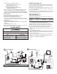
STATIC PRESSURE TEST (FIG.
1)
CASING STATIC PRESSURE TABLE
If duct static pressure cannot be set, casing static pressure should not exceed
the values listed below when taken cold.
DUCTING SYSTEM OPERATING VOLTS FLEXIBLE HARD
DC MODELS 12 0.25˝ W.C. 0.35˝ W.C.
AC MODELS 120 0.25˝ W.C. 0.35˝ W.C.
NOTE: For maximum performance and reliability refer to Installation Addendum
for manufacturer’s recommendations and specifications.
Voltage greater than indicated will cause higher static readings.
Reducing the number of duct turns and stretching ducts will increase
air flow and reduce static pressure. Adding ducts or increasing dis-
charge system (hard ducting) will also reduce static pressure.
1. With door open, locate static pressure tap or use location on back of
casing
FIG 1.
2. Shut off gas supply to furnace.
3. Insert static pressure tube onto tap and attach an incline manometer.
With door closed, pressure should not exceed values specified in
CASING STATIC PRESSURE TABLE.
4. Remove pressure tube when finished. Close door or reinstall cover.
12V DC
SUPPLY
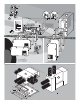
IMPORTANT: If any original wire has to be replaced, it must be replaced with type 105 C or its equivalent.
Terminal Block on 85 Models only.
BLACK
BLUE
RED
YELLOW
HIGH TENSION
+ 12V DC
NEG
RED
YELLOW
ELECTRODE
YELLOW
VALVE
RED
1
4
2
5
3
6
1
4
2
5
3
6
+THERMO
MOTOR
CIRCUIT
BREAKER
IGNITION
BOARD
BLW PWR
SAIL
SWITCH
BLUE
BLUE
LIMIT
SWITCH
WHITE
BLUE
YELLOW
RED
GROUND
THERMOSTAT
ON
OFF
ON/OFF
SWITCH
THERMO
DC Wiring Diagram
AC Wiring Diagram
RED
11
12
CUSTOMER SUPPLIED WIRING
PICTORIAL DIAGRAM
Off
On
Valve
Electrode
Green
Sail
Switch
Green
Yellow
33
22
11
White
Black
Yellow
Black
Black
Yellow
Red
Blue
Blue
Limit Switch
Blue
Red
Green
Ye l l ow
Transformer
Ignition Control
Black
Brown
Motor
120 VAC Green
120 VAC Black
120 VAC White
White
Thermo Blue
AC Capacitor Motor Run
+Thermo Blue
HIGH TENSION
DO NOT
GRIP
HERE
1
4
2
3
++
123 45 6
NOTE: Circuit Breaker and ON/OFF Switch may be
separate or combined components.