
User`s guide


Demonstration Scripts
44 M1 System Management Board User’s Guide
Voltage Monitoring
This section demonstrates how to use the System Management software to monitor the board's voltages with the
external power supply.
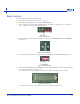
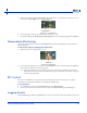
1. Observe voltages in real-time (including potentiometer) in the Board Status tab (Figure 5-9).
Figure 5-9. Board Voltage Monitoring
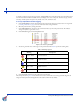
2. View the graphs in the Graphs tab. If necessary, scroll down to view the desired graph. Note that the graph may
change slowly upon connection to power.
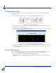
3. Observe the reading for Main Supply in the Board Supply panel (Figure 5-9). Compare this reading to the reading
for the main supply voltage in the Graphs tab (Figure 5-10).
Figure 5-10. Board Voltage Monitoring: Main Supply Graph
4. Observe the reading for 3.3 V, 5.0 V, and +12 V in the PSU Supply panel (Figure 5-9). Compare this reading to the
reading for each voltage level in the Graphs tab. You may have to scroll down for each voltage level using the scroll
bar on the right hand side.
Current Monitoring
This example demonstrates the real-time current reading for advanced technology extended (ATX) loads (+12 V, +5 V,
and +3.3 V) under the Board Status tab. ATX power supply refers to the power supply used throughout.
1. Observe the current of the main supply in real-time in the Board Status tab.
2. Compare the readings in the Board Supply panel in the Board Status tab with their corresponding graph in the
Graphs tab.