
Inc. Programmable H/C Controller Thermostat Installation Guide
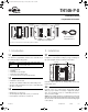

TH146-P-U 400-280-010-B 5/24/07 8/12
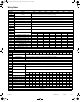
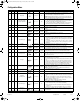
Configuration Menu
Item HP HVAC Parameters Display Options Default Description
1 √√ Time format 12 Hr / 24 Hr 24 Hr Select the time display format.
2 √√ Early Start On / OF OF
• On: Heating or cooling starts in advance (as determined by the control-
ler) so that the desired temperature is attained at the set times.
• OF (Off): Heating or cooling starts at the set times.
NOTE: Early Start applies for periods 1 and 3 (P1 and P3) only. When this
feature is enabled, heating or cooling will start in advance of the set time for
P1 and P3 but will start at the set time for P2 and P4.
3 √√
Automatic daylight
savings adjustment
OF / 1 / 2 OF
• OF (Off): The function is deactivated.
• 1 : The controller switches to daylight savings time on the first Sunday of
April and to normal time on the last Sunday of October.
• 2 : The controller switches to daylight savings time on the second Sun-
day of March and to normal time on the first Sunday of November.
4 √√ Temperature format °C / °F °C Select the temperature display format.
5 √ Balance point low
-30 to 10°C
(-22 to 50°F)
-10°C
(14°F)
Set the bP L limit (see section 4.2).
NOTE: Lower bP L below its minimum (- -) if you do not wish to use this
function.
6 √ Balance point high
-5 to 30°C
(23 to 86°F)
5°C
(41°F)
Set the bP H limit (see section 4.2).
NOTE: Raise bP H above its maximum (- -) if you do not wish to use this
function.
7 √ Defrost point
-10 to 15°C
(14 to 59°F)
10°C
(50°F)
Set the defrost point temperature (see section 4.3).
NOTE: Raise the defrost point above its maximum (- -) if you do not wish to
use this function.
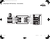
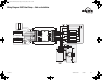
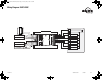
8 √ Installation type Ad / nr Ad
Set according to the type of heat pump installation (see section 4.4).
• Ad (add-on): Use this setting when the indoor coils are located down-
stream of the auxiliary heat source. This is generally the case for add-on
installations.
• nr (normal): Select this setting when the indoor coils are located
upstream of the auxiliary heat source. This is generally the case for new
installations.
9 √
Auxiliary
interstage delay
5 to 90 min. 30 min. Set the interstage delay for the auxiliary stage (see section 4.5).
10 √ Low temperature limit
-10 to 20°C
(14 to 68°F)
5°C
(41°F)
Set the low temperature limit of the plenum (see section 4.6).
NOTE: This function is not used if you lower LLMT below its minimum
(- -) or if the plenum temperature sensor is not connected to the controller.
11 √ High temperature limit
30 to 90°C
(86 to 194°F)
70°C
(158°F)
Set the high temperature limit of the plenum (see section 4.6).
NOTE: This function is not used if you raise HLMT above its maximum (- -)
or if the plenum temperature sensor is not connected to the controller.
12 √√ Cycles per hour 2 to 6 4
Select the number of heating/cooling cycles per hour. For optimal heating
control, use the setting that matches your system as follows: 3=20 min (hot
water, 90%+ high-efficiency furnace), 4=15 min (gas or oil), 5=12 min (gas
or oil), 6=10 min (electric).
13 √ Heat type GA / EL EL
This setting determines the fan operation in automatic mode when the sys-
tem is in heating mode (see section 5.3).
• EL (electric heating): The fan starts and stops at the same time as heat-
ing.
• GA (gas or oil heating): The fan starts when the temperature inside the
plenum rises above the Fan Limit (see item 14) and stops when the tem-
perature drops 12°C below the Fan Limit. NOTE: The fan will not start if
the plenum temperature sensor is not connected to the controller.
14 √ Fan limit
38 to 90°C
(100 to 194°F)
80°C
(176°F)
This parameter is available only when gas heating is selected (see item 13).
WARNING: FLMT can be used in parallel with an UL353-approved device
but they do not replace such device.
NOTE: The fan will not start if you raise FLMT above its maximum (--).
15 √√ Smart Fan On / OF OF
• On: Smart Fan is On (see section 4.7).
• OF: Smart Fan is Off.
16 √√Temperature setback
0 to 9°C
(0 to 16°F)
0°C
(0°F)
Set the amount of temperature setback when the controller is placed in
Unoccupied mode (see section 6.4).
17 √√
Humidifier
operating mode
Co / HE / Fn Fn
• Co (conventional): The humidifier will operate if the humidity is too low. If
the fan is not already On, it will turn On at the same time as the humidi-
fier.
• HE (heat): The humidifier can operate only when heating is activated.
• Fn (fan): The humidifier can operate as long as the fan is running,
whether heating is activated or not.
NOTE: The humidifier is disabled when cooling is activated.
18 √√ Dehumidifier type Co / AE / dr Co
Set according to the type of dehumidifier used.
• Co (conventional): Select this setting when using a dehumidifier (except
an air exchanger) or when you do not wish to dehumidify.
• AE (air exchanger): Select this setting when using an air exchanger (see
section 4.10).
• dr (droop): Select this setting to dehumidify by droop (see section 4.9).
19 √√
Minimum air
exchange time
0 - 60 min. 0
This parameter is available only if the controller is configured for using an
air exchanger (see item 18). Use it to set the minimum air exchange time
(see section 8.3).
Note: Only items 1 to 4 are available when the controller is placed in user mode (SW1-1 switch).
400-280-010-B (TH146-P-U) ENG.fm Page 8 Thursday, May 24, 2007 4:28 PM