367 Vorsprung durch Technik www.audi.co.uk Service Training The six-speed automatic gearbox 09D in the Audi Q7 Self-Study Programme 367 All rights reserved. Technical specifications subject to change without notice. Copyright AUDI AG I/VK-35 Service.training@audi.de Fax +49-841/89-36367 AUDI AG D-85045 Ingolstadt Technical status: 10/06 Printed in Germany A07.5S00.20.
Contents General Six-speed automatic gearbox 09D . . . . . . . . . . . . . . . . . . . . . . . . . . . . . . . . . . . . . . . . . . . . . 4 Specifications . . . . . . . . . . . . . . . . . . . . . . . . . . . . . . . . . . . . . . . . . . . . . . . . . . . . . . . . . . . . . . . . 6 Sectional view of gearbox 09D . . . . . . . . . . . . . . . . . . . . . . . . . . . . . . . . . . . . . . . . . . . . . . . . 8 Components diagram . . . . . . . . . . . . . . . . . . . . . . . . . . . . . . . . . . . .
Gearbox control unit Functional diagram of the 09D gearbox . . . . . . . . . . . . . . . . . . . . . . . . . . . . . . . . . . . . . . . . 38 Automatic gearbox control unit J217 . . . . . . . . . . . . . . . . . . . . . . . . . . . . . . . . . . . . . . . . . . 40 Multi-function switch F125 . . . . . . . . . . . . . . . . . . . . . . . . . . . . . . . . . . . . . . . . . . . . . . . . . . . 41 Gearbox input speed sender G182 . . . . . . . . . . . . . . . . . . . . . . . . . . . . . . . . . . . . . . . . . .
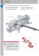
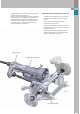
General The six-speed automatic gearbox 09D in the Audi Q7 Unlike the usual Audi longitudinal AWD gearboxes, where the front axle differential and the transfer case are integrated in an automatic or manual gearbox, six-speed automatic gearbox 09D is designed as an independent component. Rear axle differential 0AB Note In addition to the general descriptions of the 09D gearbox, this Self-Study Programme shows the special features of the gearbox in the context of the Audi Q7.
The 09D gearbox is a modern six-speed automatic gearbox of the conventional type. It derives from the VW Touareg, in which it has been very successful, and is notable in particular for its compact build and robustness. The 09D gearbox can transmit up to 750 Nm of engine torque, and is currently used in combination with the most powerful engines in the Audi Q7. Special features designed for off-road use – A special low ATF intake point and a high ATF capacity ensure reliable oil intake in rough terrain.
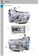
General Specifications Gearbox breather 367_008 Spare part no. AISIN model no.
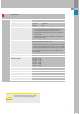
Specifications Developer/manufacturer AISIN AW CO.
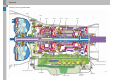
General Cutaway view of gearbox 09D ATF pump Brake B1 Clutch K3 Clutch K1 Freewheel Brake B2 Clutch K2 Locking pawl for parking lock Gearbox output speed sender G195 Gearbox input speed sender G182 367_011 ATF strainer/filter Shift solenoid 8 Manual selector lever ATF intake connection Electrical pressure control valve
Components diagram Automatic gearbox control unit J217 Gear selector Connector for sensors Connector for actuators Multi-function switch F125 Connection to gearbox input speed sender G182 Connection to gearbox output speed sender G195 Gearbox oil temperature sensor G93 Hydraulic control (valve assembly) 367_066 Electromagnetic valves (actuators) Bottom view of the gearbox - looking at the hydraulic control (valve assembly) Legend to sectional view of gearbox Hydraulic parts, hydraulic control, ATF
Gearbox subassemblies Torque converter In an 09D gearbox, torque is transmitted from the engine to the gearbox by a hydrodynamic torque converter with slip-controlled lockup clutch. They differ in respect of their… … size (capacity), … torque conversion factor, … torque converter characteristic, … torsion damper and … lockup clutch configuration. Different types of torque converter are used depending on engine power output and characteristics.
Mounting instructions Pinion Ring gear Fitting size - torque converter ATF pump Driver Pinion Driver Torque converter hub 367_071 ATF pump (removed) Roller bearing Note Always make sure that the fitting bushes are installed correctly between the engine and the gearbox. Missing fitting bushes will result in irreparable damage to the roller bearing, the torque converter hub and the shaft oil seal due to offset between the engine and the gearbox.
Gearbox subassemblies Torque converter lockup clutch Design The torque converter has a lockup clutch with integrated torsion dampers. The torsion dampers reduce torsional vibration when the torque converter lockup clutch is closed. This allows the operating range "converter lockup clutch closed" to be extended.
Controlled operation Engine load At defined operating points, the lockup clutch is operated with a low slip (controlled operation). Controlled operation provides better fuel economy than with the converter lockup clutch open, and better ride comfort than with the converter lockup clutch closed.
Gearbox subassemblies Oil supply/lubrication ATF (Automatic Transmission Fluid) As mentioned previously, taking the drive concept of the Audi Q7 as a basis, the 09D gearbox is designed as an independent component, without the usual integrated transfer case and front axle differential. This is why the 09D gearbox only has a single ATF oil supply. The exacting requirements with regard to shift quality, functional reliability and ease of maintenance put extreme demands on the ATF.
Ring gear Pinion ATF pump housing Driver Thrust plate Roller bearing Stator shaft 367_053 One of the key components of an automatic gearbox is the ATF pump. The gearbox cannot function properly without a sufficient supply of oil. 367_094 It is directly driven by the engine (at engine speed) via the converter housing and the converter hub. Two driver grooves on the torque converter hub engage the pinion drivers. The torque converter hub runs on low-friction bearings in the pump housing.
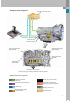
Gearbox subassemblies ATF cooling ATF cooling is thermostat-controlled by means of an oil-to-air heat exchanger (ATF cooler). The ATF cooler located in front of the engine cooler and the air conditioning compressor, as seen in the direction of travel. ATF cooler Oil temperature regulator (thermostat) ATF cooler supply line ATF cooler return line Oil temperature regulator (thermostat) The thermostat is integrated in the supply and return lines of the ATF cooling system.
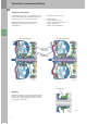
Thermostat closed Bypass Expanding wax element G K G K The expanding wax element also acts as the thermostat slide valve and regulates the ATF feed to the cooler. In the closed state, a small fraction of the ATF flows through the bypass, thereby heating the expanding wax element. At a temperature of approx. 75 °C, the plunger of the expanding wax element begins to press downwards against the force of the spring, thereby opening the inlet to the cooler (see next figure).
Gearbox subassemblies Planetary gearbox Sun gear S1 The 09D gearbox is based on the Lepelletier planetary gear set concept (6 forward gears and R gear). The Lepelletier planetary gear set is based on a single planetary gear set (primary planetary gear set) and a Ravigneaux planetary gear set further down the drive train (secondary planetary gear set).
The special feature of the Lepelletier planetary gear set is that the sun gears and the planet carrier of the Ravigneaux gear set are driven at different speeds. This allows a large number of ratios to be realised. Inner plate carrier Clutch K3 Planet carrier PT1 The sun gears of the Ravigneaux gear seat are driven at the reduced output speed of the single planetary gear set. The planet carrier of the Ravigneaux gear seat is driven at gearbox input speed.
Gearbox subassemblies Shift elements A continuous flow of power and different ratios can be obtained in a planetary gear set by introducing torque into a corresponding component (e.g. on the planet carrier) and holding a different component stationary (e.g. the sun gear) or interconnecting two components of a planetary gear set (e.g. connecting the planet carrier to the sun gear).
Brake B2 Clutch K2 Outer plate carrier of clutch K2 (pulled back slightly to provide a better view of K2) Freewheel F 367_020 367_073 These tasks are performed by the so-called shift elements (clutches/brakes). The shift elements, in combination with the planetary gear sets, establish a flow of power and execute gear shifts under load, without any interruption in tractive power.
Gearbox subassemblies Overview of planetary gearbox/shift elements K1 K3 P1 K2 P3 S2 S3 367_021 PT1 Lockup clutch B1 H1 S1 H2 F P2 PT2 B2 Schematic power flow diagram 367_022 22
Primary planetary gear set Component: connected to: H1 P1 S1 PT1 Turbine shaft (drive)/clutch K2 Power transmission in planetary gear set Stationary Clutches K1 and K3 – – – – Ring gear 1 Planetary gears 1 Sun gear 1 Planet carrier 1 Secondary planetary gear set Component: connected to: H2 P2 P3 S2 S3 PT2 Output Power transmission in planetary gear set Power transmission in planetary gear set Clutch K3/brake B1 Clutch K1 Clutch K2/brake B2/freewheel F – – – – – – Ring gear 2 Planetary gears 2, lo
Gearbox subassemblies Function of the shift elements Clutches and brakes The function of the shift elements is explained here using clutch K2, which is exemplary of clutches K1 and K3, as well as brakes B1 and B2. Unlike the clutches, the brakes require no dynamic pressure compensation, because their clutch pistons and cylinders are non-rotating, and therefore are not subject to a dynamic increase in pressure (refer to page 26). The shift elements are actuated hydraulically.
In order to close the clutch, oil pressure is admitted into the clutch cylinder chamber. The clutch piston compresses the clutch plate assembly, and the clutch engages when the required oil pressure is reached. If the clutch cylinder chamber is pressureless, the clutch piston is forced back into its initial position by spring pressure (in this case, by multiple coil springs).
Gearbox subassemblies Dynamic pressure compensation in the clutches At high engine speeds, due to rotation, the oil is subject to high centrifugal forces inside the clutch cylinder chamber. This causes the pressure inside the clutch cylinder chamber to increase towards the largest radius. This process is referred to as "dynamic pressure increase".
Freewheel The freewheel transmits torque in one direction of rotation only. No torque is transmitted in the opposite direction. In the 09D gearbox, the freewheel is used for driving away in 1st gear. The freewheel holds planet carrier PT2 stationary and thus allows power to flow (refer to page 31). Note Due to the freewheel, no engine braking effect is available in 1st gear during normal automatic operation.
Gearbox subassemblies Hydraulic control Valve assembly The clutches and brakes (shift elements) are controlled by the valve assembly by means of hydraulic shift control valves (so-called gate valves). The gate valves are controlled by electromagnetic valves, which, in turn, are activated by the automatic gearbox control unit J217. In addition to the shift elements, the valve assembly controls the lockup clutch and the various pressures throughout the gearbox (e.g.
Electromagnetic valves In the case of the electromagnetic valves, a distinction is made between shift solenoids with two switching positions (OPEN - CLOSE) and electronic pressure control valves (known as EPCVs or modulating valves). The shift solenoids (N88/N89) are so-called 3/2 way valves or OPEN-CLOSE valves. 3/2 valve means the valves has 3 connections and 2 switching positions (open/closed or OPEN–CLOSE). These valves are used for switching hydraulic shift control valves.
Gearbox subassemblies Shift logic Solenoid logic 3/2 valves Gear shifting component logic Electronic pressure control valves (EDS) Clutches, brakes, freewheel P N Reverse (R) gear First gear T T Third gear T/Z z Fourth gear T/Z z Fifth gear T/Z z T Second gear Sixth gear z 367_033 Function assignments of the electromagnetic valves N90 N91 N92 N93 N282 N283 Legend of solenoid valve logic: Solenoid valve is not activated (el. current approx.
Description of gear/torque curve 1st gear i = 4.148 367_023 Shift elements: clutch K1 - freewheel F The turbine shaft drives ring gear H1 of the primary planetary gear set. Ring gear H1 drives the planetary gears P1, which revolve around the stationary sun gear S1. Planet carrier PT1 is driven in this way. Clutch K1 connects PT1 to sun gear S3 and thus introduces torque into the secondary planetary gear set. Freewheel F locks planet carrier PT2.
Gearbox subassemblies 1st gear in tiptronic mode (with engine braking effect) 367_024 Shift elements: clutch K1 - brake B2 The engine braking effect can be utilised in 1st in special driving situations - e.g. on steep downhill gradients - by selecting 1st gear in tiptronic mode (B2 closed). The torque curve is as described for 1st gear (on previous page). The engine braking effect can only be utilised in 1st gear by closing brake B2. Brake B2 locks the planet carrier PT2 like freewheel F.
3rd gear i = 1.556 367_026 shift elements: clutch K1 - clutch K3 The turbine shaft drives ring gear H1 of the primary planetary gear set. Ring gear H1 drives the planetary gears P1, which revolve around the stationary sun gear S1. Planet carrier PT1 is driven in this way. Clutch K1 connects PT1 to sun gear S3 and thus introduces torque into the secondary planetary gear set. Clutch K3 likewise introduces torque into the secondary planetary gear set driving sun gear S2.
Gearbox subassemblies 5th gear i = 0.859 367_028 shift elements: clutch K2 - clutch K3 The turbine shaft drives the ring gear H1 of the primary planetary gear set and the outer plate carrier of clutch K2. Ring gear H1 drives the planetary gears P1, which revolve around the stationary sun gear S1. Planet carrier PT1 is driven in this way. Clutch K3 connects PT1 to sun gear S2, and thus introduces torque into the secondary planetary gear set.
R gear i = 3.394 367_030 shift elements: clutch K3 - brake B2 The turbine shaft drives ring gear H1 of the primary planetary gear set. Ring gear H1 drives the planetary gears P1, which revolve around the stationary sun gear S1. Planet carrier PT1 is driven in this way. Clutch K3 connects PT1 to sun gear S2, and thus introduces torque into the secondary planetary gear set. The brake B2 locks the planet carrier PT2 in place. Torque is transmitted from the sun wheel S2 to the long planetary gears P2.
Gearbox subassemblies Parking lock The parking lock is a device which prevents the vehicle from rolling away. It has a conventional (all-mechanical) design, i.e. it is actuated by the selector lever via a Bowden cable. Gearshift lever Parking lock linkage 367_040 Selector shaft The parking lock gear is rigidly connected to the gearbox output shaft. This enables the locking pawl, which engages the teeth of the parking lock gear, to lock the transfer case.
Parking lock linkage Locking pawl Retainer Return spring Parking lock gear 367_041 Parking lock linkage Retainer Stop Guides on the retainer Selector lever positions R/N/D/S In selector lever positions R/N/D/S, the parking lock linkage is in a position in which the taper is not engaging the locking pawl. The locking pawl is held in an initial position with sufficient clearance to the teeth of the parking lock gear by the return spring.
Gearbox control unit Function diagram of the 09D gearbox on the Audi Q7 (as at May 2007) Switch for P/N signal Shift matrix F125 R signal to the self-diagnostics R signal to J519 and Y7 (refer to page 53) P/N signal to J518, prerequisite for controlling term.
Note Always use the current version of the current flow diagram to troubleshoot the vehicle.
Gearbox control unit Automatic gearbox control unit J217 The gearbox control unit on the Audi Q7 is located under the front right seat below onboard power supply control unit 2 J520. The control unit is manufactured by Japanese gearbox specialist AISIN AW Co., Ltd. Update programming is possible with the VAS 5051. Note After replacing the gearbox control unit, the basic setting procedure must be performed using the diagnostic tester (under "Guided Fault Finding").
Multi-function switch F125 367_042 Multi-function switch F125 Multi-function switch F125 has the following tasks and controls the following functions: Connector C (on wiring harness) – Starter inhibitor control (see function diagram) – P/N lock control (activation of shift lock solenoid N110) – It identifies the vehicle operating states forward/ reverse/neutral/sport program, and this information is used by the gearbox control unit J217 for controlling the gearbox – It identifies reversing or the inten
Gearbox control unit Contact assignments of the multi-function switch The multi-function switch is a mechanical multiposition switch with 6 sliding contacts: Switch for positions "P" and "N" Reversing switch F41 – 4 switches for identification of the selector valve position and selector lever position – 1 switch for activating the functions relevant to reversing (F41) – 1 switch for starter control in selector lever positions "P" and "N" Since the switch contact is fully mechanical, F125 can be checked
Setting multi-function switch F125 Use setting gauge T1073 to set the multi-function switch. Please follow the instructions given in the Workshop Manual. Setting gauge T10173 367_044 Note Special care must be taken to ensure that the correct torque is applied to the contact lever adjusting nut. If the nut is over-torqued, the multi-function switch will move stiffly and the rubber seals will be damaged. If the nut is not tightened sufficiently, this can lead to leaking of the multifunction switch.
Gearbox control unit Gearbox input speed sender G182 Note G182 is integrated in the ATF pump housing and measures the direct gearbox input speed (turbine speed) by means of a ring gear on the gearbox input shaft. Due to torque converter slip, the gearbox input speed (turbine speed) is not equivalent to the engine speed (except when the torque converter lockup clutch is fully closed).
Function - sender G182 Sender G182 is based on the Hall principle. The output signal is a square-wave signal whose frequency is proportional to turbine speed. Voltage supply Ground and signal 367_037 DSO image - signal from G182 367_057 Voltage level when the turbine shaft is stationary, i.
Gearbox control unit Gearbox output speed sender G195 G195 is located behind the valve assembly. It is bolted to the gearbox housing and measures the gearbox output speed at the ring gear of the Ravigneaux planetary gear set. The ring gear has special milled recesses for this purpose, and serves as an encoder disc. One of the principal signals of the electronic gearbox control system is the gearbox output speed. There is a direct correlation between gearbox output speed and driving speed.
Function - sender G195 Sender G182 is based on the Hall principle. The output signal is a square-wave signal, the frequency of which is a function of gearbox output speed (driving speed).
Gearbox control unit Gearbox oil temperature sensor G93 G93 is integrated inside the valve assembly and is swept by ATF. It generates an ATF temperature signal for the automatic gearbox control unit J217. G93 is an NTC resistor and an integral part of the wiring harness.
Wiring harness incl. G93 G93 NTC resistor characteristic of the G93 Resistor in Ω Wiring harness sensors in the gearbox Temperature in °C 367_060 Connector B – Pins 1 and 2 for G93 Protective/substitute function in case of failure: – A substitute value is generated from the engine temperature and operating time.
Gearbox control unit CAN information exchange with the 09D gearbox on the Audi Q7 J217 – Automatic gearbox control unit System status ● Fault memory entry/status ● Selector mechanism active ● Coding in engine control unit ● Momentary gear or target gear ● Selector lever position ● Motion resistance index ● Information on emergency running mode and self-diagnosis ● OBD status ● Nominal idling speed ● Torque gradient limitation (converter/gearbox protection) ● Converter/gearbox protecti
J104 – ESP control unit JXXX* – engine control unit ● Accelerator pedal angle ● Kick-down ● Engine torque data (nominal/actual) ● Lateral acceleration ● ABS, TCS and ESP intervention ● TCS shift control ● Wheel speeds (front left, front right, rear left, rear right) ● System status ● ABS warning lamp "on" ● ESP in passive mode ● Engine speed ● Driver torque input ● Coolant temperature ● Brake light/brake pedal switch ● Air conditioning system activation ● CCS status ● Altit
Gearbox control unit Interfaces/auxiliary signals Kick-down information There is no separate switch for kick-down information. A "force element" is integrated in the accelerator position sender in place of a stop buffer (for manual gearboxes). The force element produces a "mechanical pressure point" which conveys an authentic "kickdown feel" to the driver. When the driver engages the kickdown, the full-load voltage of the accelerator position senders G79 and G185 is exceeded.
Distributed functions in the Audi Q7 Starter inhibitor/starter control Reversing switch F41 The starter control/starter inhibitor function is implemented via entry and start authorisation control unit J518. The reversing switch F41 is integrated in the multifunction switch F125. F41 supplies a voltage signal (R signal) to the onboard power supply control unit J519 and other control units which utilise the R signal.
Gearbox control unit tiptronic shift strategy – Automatic upshift upon reaching maximum engine speed 1) The vehicle is normally driven away in first gear. It can also be driven away in second gear by shifting up into second before setting off (with steering wheel tiptronic or selector lever). This makes driving away easier on low friction road surfaces, e.g. on icy or snow-covered roads.
Limp-home mode In the event of faults/malfunctions which activate the mechanical limp-home mode, 3rd gear is always selected during vehicle operation in any gear up to third. If the gearbox is already in fourth, fifth or sixth gear, the momentary gear is maintained until the selector lever is moved into neutral or the ignition turned off. When driving away again or restarting the engine in selector lever position "D" or "S", third gear is always selected.
Gearbox control unit Gearbox adaption (09D gearbox) Introduction A prerequisite for good and consistent shift quality, in additon to the design, is precision control of the shift elements. This is the purpose of the gearbox adaption feature. In order to maintain constant shift quality during the entire service life of the gearbox, it is necessary to continuously adapt the various open and closed-loop control parameters and save acquired adaption data.
Mechanical and hydraulic influencing factors The shift elements are actuated hydraulically. For this purpose, allowance must be made for the characteristics of the electrical and mechanical control valves. The resistances produced by mechanical friction in components, as well as the pressure of the piston resetting springs, have to be overcome. In addition, attention must be paid to the filling of all ports, lines and cylinder chambers, as well as the clutch clearance.
Gearbox control unit Upshift under acceleration sequence Legend n_mot = engine speed n_t = turbine speed m_mot = engine torque P_zu = engaging clutch P_ab = disengaging clutch t = time A, B, C = adaption range Quick filling time (quick filling) Filling pressure A Pre-filling B Shift pressure C Holding pressure 367_114 The following aspects of the gearshift sequence are adapted: Certain adaption conditions have to be met so that adaptions can be performed: – Quick filling time (pre-filling)
Deleting adaption values Adaption drive The adaption values of the 09D gearbox are preserved even if the power supply to the gearbox control unit is cut off (e.g. battery is disconnected, etc.). However, they can be deleted using the "Basic setting 04" function on the diagnostic tester. Step 1: Firstly, the aforementioned adaption conditions must be fulfilled.
Gearbox periphery Gear selector The gearshift mechanism is connected mechanically to the automatic gearbox via the selector lever cable. It also performs several tasks and functions, for which an electrical connection exists to the gearbox control unit and the vehicle periphery.
The design and functioning of the gearshift mechanism on the Audi Q7 are largely identical to the gearshift mechanism on the Audi A6 ´05 (up to approx. mid-2006). Here are the main differences: When replacing the gearshift mechanism, the selector housing (fitted from the outside) remains in the vehicle. Only the function unit of the gearshift mechanism needs to be replaced. The gearshift mechanism can be removed from the interior of the vehicle in order to make repairs (e.g. to replace microswitch F305).
Gearbox periphery Shift locks (P lock and P/N lock) Basically, a distinction is made between the P/N lock while driving and the P/N lock with the ignition "on" and locking of the selector lever in the "P" position with the ignition key removed (P lock). View from the right The kinematics of the locking mechanism are designed in such a way that locking is possible both in the deenergised state of the N110 (position "P") and in the energised state (position "N").
Shift lock in selector lever position "P" Locking of the selector lever in lever position "P" is ensured by the automatic locking of the stop lever in this position. To release the shift lock, solenoid N110 is energised, with the result that the solenoid pushes the stop lever back out of the P lock. If solenoid N110 is deenergised, the stop lever, assisted by a spring in solenoid N110, drops automatically under gravity into the P lock as soon as the selector lever is moved into position "P".
Gearbox periphery Emergency release of the P lock Due to the fact that the P lock is only unlocked when solenoid N110 is activated, the selector lever remains locked in position "P" in the event of a malfunction (e.g. flat battery, failure of solenoid N110, etc.). To enable the vehicle to be moved in such a situation, there is an emergency release lever on the left-hand side of the stop lever. The emergency release mechanism can be accessed by removing the ashtray insert and the trim clip behind it.
Ignition key withdrawal lock The ignition key withdrawal lock is realised automatically by a mechanical locking mechanism integrated in the entry and start authorisation switch E415. Microswitch 1 with resistor The ignition key withdrawal lock is released electromechanically by brief activation of the ignition key withdrawal lock solenoid N376. For this purpose, switch E415 requires information on selector lever position "P".
Gearbox periphery Selector lever sensor system J587 The functions of the selector lever sensor system J587 are limited to generating the tiptronic signal for the tiptronic function (from F189) and the P/R/N/D/S signal for activating the selector lever position indicator unit Y26. A defined signal frequency is assigned to each selector lever position (see DSO images).
DSO images of the P/R/N/D/S signals DSO connection: – black probe tip – red probe tip * Pin 6* Pin 9* Pin on connector A or test adapter V.A.G. 1598/42 Test equipment: – V.A.G 1598/54 with – V.A.
Gearbox periphery tiptronic signal The information selector lever in tiptronic gate, selector lever in Tip+ position or selector lever in Tip– position is transferred via a discrete line (see DSO images) to the gearbox control unit in the form of a frequency-modulated square-wave signal (FMR signal). Advantages of this new feature: – Higher operational reliability - only one line to the control unit is required (instead of three), thereby reducing the number of potential sources of fault.
Glossary Glossary Ratio spread In the context of gearboxes, the "spread" of a gearbox is its "range of ratios". The ratio spread is the ratio of the lowest (first) and highest (sixth) gear ratios. The ratio spread value is obtained by dividing the first gear ratio by the highest gear ratio (in this case, 6th gear). Example (using the 09G gearbox): i First gear 4.148 i Sixth gear 0.686 4.148 : 0.686 = 6.
Index A Adaption . . . . . . . . . . . . . . . . . . . . . . . . . . . . . . . . . . Adaption conditions . . . . . . . . . . . . . . . . . . . . . . . . Adaption drive . . . . . . . . . . . . . . . . . . . . . . . . . . . . . ATF (Automatic Transmission Fluid). . . . . . . . . . . . ATF cooling . . . . . . . . . . . . . . . . . . . . . . . . . . . . . . . . ATF pump . . . . . . . . . . . . . . . . . . . . . . . . . . . . . . . . . ATF temperature. . . . . . . . . . . . . . . . . . . . . . . . . . . .
K R Kick-down information . . . . . . . . . . . . . . . . . . . . . . 52 Ratio spread . . . . . . . . . . . . . . . . . . . . . . . . . . . . . . . 7 Reversing light . . . . . . . . . . . . . . . . . . . . . . . . . . . . . 53 Reversing switch F41 . . . . . . . . . . . . . . . . . . . . . . . . 53 R gear . . . . . . . . . . . . . . . . . . . . . . . . . . . . . . . . . . . . . 35 L Lepelletier planetary gear set . . . . . . . . . . . . . . . . 18 Limp-home mode . . . . . . . . . . . . . . . . . . . . .
367 Vorsprung durch Technik www.audi.co.uk Service Training The six-speed automatic gearbox 09D in the Audi Q7 Self-Study Programme 367 All rights reserved. Technical specifications subject to change without notice. Copyright AUDI AG I/VK-35 Service.training@audi.de Fax +49-841/89-36367 AUDI AG D-85045 Ingolstadt Technical status: 10/06 Printed in Germany A07.5S00.20.