
Self-Study Program

45
367_057
367_037
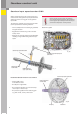
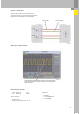
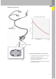
DSO connection for G182
– black probe tip pin 1
– red probe tip pin 39
Test conditions:
– Engine idling
– Selector lever position "N" or "P"
Auxiliaries:
– VAS 5051
– V.A.G 1598/48 with
– V.A.G 1598/42
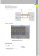
Voltage level when the turbine shaft is stationary, i.e gear selected, driving
speed 0 kph (depending on whether a tooth space or a tooth is located in
front of the sensor)
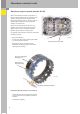
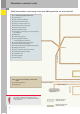
Function - sender G182
Sender G182 is based on the Hall principle.
The output signal is a square-wave signal whose
frequency is proportional to turbine speed.
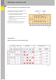
DSO image - signal from G182
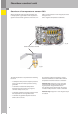
Voltage supply
Ground and signal