
Self-Study Program

66
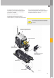
367_005
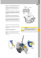
Gearbox periphery
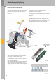
Selector lever sensor system
J587
The functions of the selector lever sensor system
J587 are limited to generating the tiptronic signal
for the tiptronic function (from F189) and the
P/R/N/D/S signal for activating the selector lever
position indicator unit Y26.
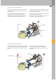
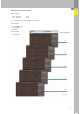
P/R/N/D/S signal
The information on the selector lever position
(P/R/N/D/S signal) is sent from the gearbox control
unit to the selector lever sensor system in the form
of a frequency-modulated square-wave signal (FMR
signal). The relevant LEDs on display unit Y26 are
then activated.
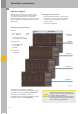
A defined signal frequency is assigned to each
selector lever position (see DSO images).
The selector lever sensor system evaluates the
signal and activates the relevant LED on display
unit Y26 (ground activation), see also page 64.
The advantages of this new feature are:
– Synchronous indication of the selector lever
position in the dash panel insert and on the
selector lever.
– Cost savings through simplification of the
selector lever sensor system control unit J587
(elimination of additional Hall sensors).
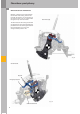
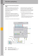
Functional diagram of the gear selector mechanism with 09D gearbox
F189 tiptronic switch
F305 Gear selector position P switch
J587 Selector lever sensor system control unit
N110 Selector lever lock solenoid
Y26 Selector lever position indicator unit
tiptronic signal
P/R/N/D/S signal