
Self-Study Program

68
Reference
For further information about the tiptronic
signal and tiptronic switch F189, please refer
to SSP 291 (page 50 onwards).
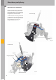
The selector mechanism has the same basic
functions as that on the Audi A3‘04, having
only a different signal waveform.
tiptronic signal
The information selector lever in tiptronic gate,
selector lever in Tip+ position or selector lever in
Tip– position is transferred via a discrete line
(see DSO images) to the gearbox control unit in the
form of a frequency-modulated square-wave signal
(FMR signal).
Advantages of this new feature:
– Higher operational reliability - only one line to
the control unit is required (instead of three),
thereby reducing the number of potential
sources of fault.
– Improved self-diagnosis
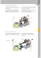
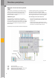
DSO images of the tiptronic signal
DSO port:
– black probe tip Pin 6*
– red probe tip Pin 3*
* Pin on connector A or
test adapter V.A.G. 1598/42
Test equipment:
– V.A.G 1598/54 with
– V.A.G 1598/42
– VAS 5051
Test conditions:
– Ignition "ON"
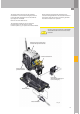
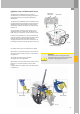
Gearbox periphery
Test adaptor V.A.G 1598/54 is available in
combination with test box V.A.G 1598/42 for testing
the signals to and from the gearshift mechanism.
Test adaptor V.A.G 1598/48 is available in
combination with test box V.A.G 1598/42 for testing
the signals to and from the 09D gearbox.
367_007
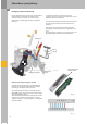
Selector lever
positions
P/R/N/D/S
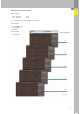
tiptronic gate
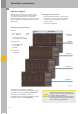
tiptronic Tip +
tiptronic Tip –