326 Vorsprung durch Technik www.audi.co.uk Service Training Audi A6 ‘05 – Electrics Self-Study Programme 326 All rights reserved. Subject to technical change. Copyright AUDI AG I/VK-35 Service.training@audi.de Fax +49-841/89-36367 AUDI AG D-85045 Ingolstadt Technical release 01/04 Printed in Germany A04.5S00.09.
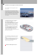
The Audi A6 – the most progressive vehicle takes the lead The new Audi A6 – the most progressive vehicle takes the lead. The new Audi A6 consistently adopts the highly networked electronic architecture, which is already used in the Audi A8. Overall, new technologies allow the A6 to match up with its "model" vehicle, the Audi A8. Features, which were previously reserved for luxury vehicles, are now also available in the topclass segment.
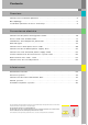
Contents Overview Control unit installation positions . . . . . . . . . . . . . . . . . . . . . . . . . . . . . . . . . . . . . . . 4 Bus topology. . . . . . . . . . . . . . . . . . . . . . . . . . . . . . . . . . . . . . . . . . . . . . . . . . . . . . . . . . 6 Installation positions of fuses and relays . . . . . . . . . . . . . . . . . . . . . . . . . . . . . . . . . 8 Convenience electrics Control unit for power management J644 . . . . . . . . . . . . . . . . . . . . . . . . . . . . . . .
Overview Control unit installation positions 1 2 3 4 5 6 7 8 9 10 11 12 4 Auxiliary heating control unit J364 Control unit for ABS with EDL J104 Control unit for distance control J428 Transmitter unit in wheel well for tyre pressure monitoring, front left G431 Control unit for on-board power supply J519 Door control unit, driver's side J386 Control unit for access and start authorisation J518 Control unit in dash panel insert J285 Control unit for steering column electronics J527 Control unit for teleph
326_146 18 Rotation rate sensor 202 19 Door control unit, passenger's side J387 20 Control unit for seat adjustment with memory, passenger’s side, J521 21 Door control unit, rear right J389 22 Transmitter unit in wheel well for tyre pressure monitoring, rear left G433 23 Radio receiver for auxiliary heating R64 24 Control unit for navigation with CD drive J401 Control unit for voice input J507 Digital sound package control unit J525 Radio R TV tuner R78 Digital radio R147 25 Transmitter unit in wheel well
Overview Bus topology Distance control J428 Control unit in dash panel insert J285 Data bus diagnosis for data bus J533 Diagnosis connection T16 NOX sensor J583 Engine electronics 1 J623 Door control unit, driver’s side J386 Power management J644 Rotation rate sensor G202 ABS with EDL J104 Door control unit, passenger’s side J387 Auxiliary heating J364 Seat occupied recognition J706 Airbag J234 Door control unit, rear left J388 Parking aid J446 Automatic transmission J217 Door control unit
Telephone transmitter and for telephone R36 Handset for telephone R37 Telephone/ telematics J526 Display and operating unit for front information J523 Navigation with CD drive J401 TV tuner R78 CD changer R41 Digital sound package J525 Radio module R Voice input J507 MOST bus CAN Instrument cluster Switch for access and start authorisation E415 Antenna read-in unit for keyless access authorisation J723 CAN Diagnosis CAN Drive CAN Convenience Wiper motor J400 Sensor for rain and light detection
Overview Installation positions of fuses and relays 1 E box in radiator tank, left 2 Relay and fuse holder behind dash panel, left 3 Fuse holder in dash panel, left 4 Main fuse carrier in radiator tank, right 5 Fuse holder in dash panel, right 6 Relay and fuse holder in the boot, right 8
326_148 9
Convenience electrics Control unit for power management J644 The basic design of the control unit for power management is the same as the control unit used in the Audi A8 ‘03. It is installed in the boot well, next to the battery. This control unit has been adapted for use in the Audi A6 ’05 in that it now has revised software, which shows the battery condition rather than the battery charge level in the MMI display. Furthermore, the diagnosis tester can be used to read out history data, i.e.
History data The diagnosis tester can be used to read out data from the control unit for power management, which makes it much easier to analyse the on-board power supply and the battery. Steady battery discharge The battery condition is 100 % when the battery is charged. As soon as cut-off level 1 is activated, the MMI "Battery condition" display drops to 90 % and then goes down to 60 % in steps.
Convenience electrics Access and start authorisation Function diagram Legend E369 E408 E415 Central locking button for outer door handle, driver’s side* Central locking button for outer door handle, passenger’s side* Central locking button for outer door handle, rear left* Central locking button for outer door handle, rear right* Button for access and start authorisation Switch for access and start authorisation F272 F273 F274 F275 F305 Outer door handle switch, driver’s door* Outer door handle switch,
326_038 15
Convenience electrics System overview The Advanced Key system was introduced with the Audi A8 '03 and has been fundamentally revised for the Audi A6 ’05. The most important new feature is that the control unit for access and start authorisation has been combined with the actuator for steering column locking.
1 Door control unit, driver's side J386 2 Control unit for on-board power supply J519 3 Control unit for access and start authorisation J518 4 Switch for access and start authorisation E415 5 Central locking button for outer door handle, driver's side E369 Outer door handle switch in driver’s door F272 Sensor for outer door handle contact, driver’s side G415 6 Antenna read-in unit for keyless access authorisation J723 7 Antenna on driver’s side for access and start authorisation R134 8 Door control unit, re
Convenience electrics Division of functions System control is broken down into three basic modules: – the control unit for access and start authorisation J518, – the antenna read-in unit for keyless access authorisation J723 and – the switch for access and start authorisation E415. All three components communicate with each other over a local single-wire bus. The control unit for access and start authorisation is the master of the system and a participant on Convenience.
Switch for access and start authorisation E415 Versions The switch for access and start authorisation is available in the following versions: – with and without Advanced Key function – with and without ignition key anti-removal lock – for radio frequencies of 315 MHz, 433 MHz or 868 MHz Functions Emergency release 326_122 The switch for access and start authorisation includes other functions apart from the ignition switch function: – Evaluation of the key position of the ignition switch: The ignition s
Convenience electrics – Reading in position P of the automatic transmission from the switch for gearbox position P F305: The signal is used to activate the integrated, magnetic ignition key anti-removal lock. If the vehicle battery is flat, the key can be removed by pressing the mechanical emergency release.
Control unit for access and start authorisation J518 The electromechanical steering column lock was integrated into the control unit for access and start authorisation. Functions – Terminal control: The control unit for access and start authorisation puts the information about terminal 15, 75x, 50, S and P on CAN Convenience. The control unit also activates the relays for terminal 15 and 75x and passes the start request signal on to the engine control unit.
Convenience electrics – CAN Communication: The control unit is a participant on CAN Convenience. Data exchange between all the components of the access and start authorisation system is performed via the control unit. It is also the diagnosis interface for the components involved. All data, e.g. code, immobiliser data, etc. is stored in the control unit for access and start authorisation.
Vehicle key The key has a mechanically coded hinged bit for the lock cylinder in the driver’s door and the tailgate/ boot lid. The transponder function is integrated into the electronics and also works without a battery. An integrated battery powers the electronics for the radio remote control and Advanced Key functions.
Convenience electrics Antenna read-in unit for keyless access authorisation J723 The control unit is only installed together with the Advanced Key option. It is located at the right of the dash panel, behind the glove compartment. It evaluates the signals from the outer door handle sensors and then activates the antennae for access and start authorisation.
Antennae for access and start authorisation E134 - R138 Four transmitting antennae are distributed in the vehicle and are used by the vehicle for radio communication with the vehicle key. The antennae transmit on a frequency of 24.5 kHz. The vehicle key evaluates all four signals and determines the position in or on the vehicle based on the field strength of the individual antennae.
Convenience electrics Opening the vehicle Antenna for central locking and anti-theft warning system R47 Antenna on passenger’s side for access start authorisation R135 Antenna on driver’s side for access start authorisation R134 Passenger compartment antenna 1 for start authorisation R138 Boot antenna for access start authorisation R137 Switch for access and start authorisation E415 Control unit for access and start authorisation J518 Antenna read-in unit for keyless access authorisation J723 Door
1 The driver puts his/her hand into the finger well of the door handle. The sensor for outer door handle contact G415 sends the information "Finger in finger well" to the antenna read-in unit for keyless access authorisation J723. 6 The control unit for access and start authorisation sends the information "Opening vehicle" on to the central control unit for the convenience system J393 and to the door control unit, whose door handle initiated the key query.
Convenience electrics Starting the vehicle using the button Antenna for central locking and anti-theft warning system R47 Antenna on passenger’s side for access start authorisation R135 Boot antenna for access start authorisation R137 Antenna on driver’s side for access start authorisation R134 Button for access and start authorisation J408 Control unit for access and start authorisation J518 Data bus diagnosis for data bus J533 Passenger compartment antenna 1 for access and start authorisation R13
1 The driver presses the button for access and start authorisation E408 down fully. The button sends the information about "Ignition on" and "Engine start" both to the switch for access and start authorisation E415 and to the control unit for access and start authorisation J518. 2 The switch for access and start authorisation passes the information from the button on to the control unit for access and start authorisation via the data lead. The two button information messages are compared there.
Convenience electrics Immobiliser and component protection Immobiliser 4 E415 J518 J533 J623 326_099 The immobiliser 4 technology is used in the Audi A6 ’05. Control unit, which is not integrated into the immobiliser This means that all components must be "taught" online, as is already the case with the Audi A8 ´03 and the Audi A3 ´04.
New identity As is already the case with the Audi A8 ‘03 , if a control unit is stolen, it is no longer necessary (for safety reasons) to also replace the remaining control units, which are integrated in the immobiliser. In this case, the "New Identity" function must be used for the control unit for access and start authorisation and the engine control unit. It is only a matter of installing a new lock set before using the "New Identity" function.
Convenience electrics External lights Front headlights Three different front headlights are used in the Audi A6 ’05: – Halogen headlights – Bi-xenon headlights – Adaptive light Halogen headlights Halogen headlights come as standard.
Bi-xenon headlights Bi-xenon headlights are installed with the "XenonPlus" option. The following lamps are fitted in the bi-xenon headlight: – A blue W5W lamp for the parking light. The colour of the parking light thus corresponds to the xenon light. – A D2S lamp for high beam headlight, headlight flasher and dipped beam headlight. The covers for dipped beam are also activated for high beam and headlight flasher operation. – A P21W lamp for the daytime driving light. This comes on dimmed to 90 %.
Convenience electrics Adaptive light The adaptive light works as a dynamic cornersensitive headlight. With the dynamic cornering headlight, the headlight projection module is pivoted horizontally by an integrated motor. The headlight lenses and the bracket do not turn. The pivot angle is approx. 15° on the inner curve side and 7.5° on the outer curve side. Pivot range 326_076 The various pivot angles have advantages in that they provide better lighting for corner routes.
Internal structure The pivot angle is monitored by an inductive pickup in the pivot module. The pickup value is evaluated immediately in the relevant power module for headlights as a pulse width-modulated signal. If the motor or pickup does not function, the power module sends an error message to the control unit for headlight range control J431. This is communicated to the driver in a display in dash panel insert J285.
Convenience electrics Signal and data exchange The same sensors that are used for dynamic headlight range control for bi-xenon headlights are also used as level sensors. They send a pulse width-modulated signal to the control unit for headlight range control. Data is exchanged between the control unit for headlight range control J431 and the power modules in the headlight on the left J667 and right J668 via a 500-kBaud CAN.
Back lights Different tail lights are used in the Audi A6 ’05, depending on the equipment variant. This is differentiated into the following: – Basic variant ECE – High variant ECE – High variant SAE Basic variant ECE The tail light in the basic variant only uses lamps with a 15-mm bayonet socket for the lights. There are three sections for tail light activation.
Convenience electrics High variant ECE These back lights are installed if bi-xenon headlights at least are fitted as the front headlights. The external feature of the High back lights is the use of LEDs for the brake light. The LEDs, which are fixed in the reflector housing, are activated by two contacts from the lamp bracket. The rear fog light is located at the bottom of the back light.
High variant SAE The back lights for the North American market have standard LED units. The LED units are used for the indicator and brake light function. The three sections underneath are for the tail light lamps. The SAE back lights have two rear fog lights and two reversing lights. Brake light and direction indicator light Rear fog light Tail lights Reversing light 326_142 LED unit diagnosis The failure of an LED is detected by the electronics in the lamp housing.
Convenience electrics Control unit in dash panel insert J285 326_145 The control unit in dash panel insert J285 is available in two variants. The High-Line variant with colour display only comes in vehicles with adaptive cruise control. As in the A8 '03, the anti-drive-off feature and gateway are no longer integrated into the dash panel insert.
Function diagram 326_037 Legend E493 Operating button for dash panel insert F1 F34 E66 F77 Oil pressure switch Warning contact for brake fluid level Switch for low coolant display Warning contact for windscreen washer level G G6 G17 G34 G35 G169 G266 Sender for fuel level indicator Pre-feed fuel pump Temperature sensor for outside temperature Sensor for brake pad wear, front left Sensor for brake pad wear, front right Fuel level sensor 2* Oil level and oil temperature sensor J17 J285 J489 J533 J540 F
Convenience electrics Control unit for on-board power supply J519 Functions The main function of the control unit for on-board power supply is to read in switch information and activate power outputs. It is familiar from the Audi A8 ‘03 and has been adapted to new functionalities in the Audi A6 ´05. 326_107 Master functions The following master functions are implemented in the control unit for on-board power supply.
Emergency function The software for the control unit for on-board power supply can be used to implement emergency functions. If a fault is detected in the rotary light switch or if there is an open circuit in the line to the rotary light switch, the control unit for on-board power supply switches the driving light on. Other functionalities In addition to the master functions, the following functions are also available in the control unit for on-board power supply.
Convenience electrics Function diagram E1 E3 E7 E18 Light switch Hazard warning light switch Fog light switch Switch for rear fog light F4 Reversing light switch F266 Contact switch for bonnet 44 G357 G358 G397 G474 G475 Sender for vertical steering column adjustm.
326_111 N395 Magnet for cover adjustment, left headlight N396 Magnet for cover adjustment, right headlight V5 V48 V49 V123 V124 V318 V319 Windscreen washer pump Left control motor for headlight range control Right control motor for headlight range control Motor for vertical steering column adjustment Motor for axial steering column adjustment Control motor for dynamic cornering light, left Control motor for dynamic cornering light, right Additional signals 1 Terminal 58 2 Terminal 58s 3 CAN Drive Hi
Convenience electrics System overview The control unit for on-board power supply J519 evaluates the following input signals: – Hall sender 1 for vertical adjustment of the steering column – Hall sender 2 for axial adjustment of the steering column – Bonnet switch for anti-theft warning system – Rotary light switch – Hazard warning button – Switch for reversing light (manual transmission) – Sensor for rain and light detection (via LIN bus) The control unit for on-board power supply J519 controls the foll
Diagnosis Basic settings After the control unit for on-board power supply J519 or the steering column or the switch for steering column adjustment E167 is replaced, a basic setting in axial and vertical position must be implemented for the steering column.
Convenience electrics Sensor for rain and light detection G397 A combined sensor for rain and light detection is used for the first time in the Audi A6 ’05. The sensor includes a light-control assistant function, which relieves the driver of the job of having to switch the driving light on manually, as well as a wiper control function, which depends on the amount of moisture on the front windscreen. The development goal here was to integrate these functions in a compact housing.
Function of the light sensor In order to detect certain ambient conditions, such as tree-lined avenues or routes through tunnels, the light sensor registers the light intensity in two areas. The global field describes the direct brightness on the vehicle, while the fore-field describes the lighting conditions in the section of road lying ahead of the vehicle. This is activated using the "Auto" setting on the rotary light switch.
Convenience electrics Function of the rain sensor The rain sensor uses the physical light refraction principle to register the amount of moisture on the windscreen. The circular LEDs integrated in the sensor emit infrared light through the windscreen from within the interior of the vehicle. LEDs Photodiode 326_091 If the windscreen is dry, the infrared light is reflected on the surface of the glass. The photodiode integrated in the centre of the sensor thus records a high light intensity.
Control unit for wiper motor J400 The control unit for wiper motor J400 was redesigned for use in the new Audi A6 ’05. As is already the case in the Audi A8 ‘03 and Audi A3 ’04, the control unit and wiper motor are integrated into one housing. It is linked to the control unit for on-board power supply J519 as a LIN-slave control unit.
Convenience electrics Control unit 2 for on-board power supply J520 An additional on-board power supply control unit is needed in the Audi A6 ´05 because of the huge range of functions it offers.
Function diagram 326_082 Legend E316 J520 N119 V1 V327 Glove compartment button Control unit 2 for on-board power supply Solenoid valve for Servotronic Motor for sliding roof Motor for glove compartment release Additional signals 1 CAN Convenience High 2 CAN Convenience Low 53
Convenience electrics Tilt sensor for anti-theft warning system The tilt sensor for the anti-theft warning system is integrated directly in control unit 2 for on-board power supply J520 in the new Audi A6 ‘05. The fluid-filled sensor registers changes in the vehicle tilt both transversely and longitudinally, thereby preventing incorrect triggering as a result of shaking through viscous fluid and electronic delay. The current tilt values can be read out using measured-value blocks.
Central control unit for convenience system J393 The central control unit for the convenience system J393, with which you may be familiar from the Audi A8 '03, is used in the Audi A6 ’05. The tasks and functions have been adapted according to requirements. The control unit is a participant on the CAN Convenience data bus.
Convenience electrics Installation position The central control unit for the convenience system is installed above the battery in the rear right of the boot.
Interior lighting control Standard equipment function The standard function includes activating the inside light in the roof lining, the front footwell lights, the glove compartment light and the boot light. The central control unit for the convenience system J393 activates the inside light in the roof lining, the boot light and the glove compartment light directly via its own outputs and inputs.
Convenience electrics Function diagram C18 Interference filter for windscreen antenna E26 Switch for glove compartment light F124 Contact switch for lock cylinder for tailgate/boot lid, anti-theft warning system, central locking F147 Contact switch for make-up mirror driver’s side F148 Contact switch for make-up mirror passenger’s side F218 Switch for tailgate/boot lid central locking F248 Button for tailgate/boot lid lock cylinder release G273 Sensor for passenger compartment monitoring H12 58 Alar
326_120 V53 Motor for tailgate/boot lid central locking V91 Motor for rear sun blind V155 Motor for tank cap locking W6 W14 W18 W20 W35 W45 W46 Glove compartment light Illuminated make-up mirror, passenger’s side Boot light, left Illuminated make-up mirror, driver’s side Boot light, right Footwell light, rear left Footwell light, rear right X Number plate light Z1 Heated rear window Additional signals 1 CAN Convenience High 2 CAN Convenience Low 3 Brake light switch F 4 ESP brake signal from c
Convenience electrics Diagnosis The central control unit for convenience system, J393, has the usual diagnostic functions, such as read fault memory, read measured value blocks, adaptation, coding, as well as selective and sequential actuator test at its disposal.
Parking aid control unit J446 You may already be familiar with the acoustic parking aid function "APS" from the Audi A3 ´04. For use in the Audi A6 ´05, a 4-channel system with sensors on the rear bumper and an 8-channel system with sensors on the front and rear bumpers are available. Versions 326_100 The parking aid control unit will be available as 4-channel system and 8-channel system versions. Only the 4-channel version is available on the Audi A6 ’05 for the US market.
Convenience electrics Input and output signals The parking aid control unit J446 requires CAN bus messages from various control units.
Door control units J386 - J389 The door control units have a similar functionality to those used in the Audi A8 ´03 and are used in the Audi A6 ’05 with appropriately adapted functions and actuation features. The separate installation of the door control unit and the power windows motor is new here. Stand-by master function 326_102 As in the Audi A8 ´03, the door control unit on the driver’s side J386 controls central locking if the central control unit for the convenience system J393 fails.
Convenience electrics System overview The door control units receive the following input signals: – – – – Power windows switch Internal locking switch Actuating elements for central locking Actuating elements for central locking (Safe mode) – Outer door handle switch (optional) – Central locking button for outer door handle – Boot release switch E164 – Switch for remote unlocking and filler flap E204 – Child-lock button E318 – Mirror adjustment change-over switch E48 – Mirror adjustment switch E43 – Mirr
Control units for seat adjustment The control units for seat adjustment can be used to set up to 8 individual seat positions for an electrically adjustable seat. The seat positions can be stored in memory and can be set again if necessary using the memory keypad or by entering a radio code. Installation position 326_115 The control units for seat adjustment are located in the floor area under the driver’s and passenger’s seat.
Convenience electrics Input and output signals (driver’s seat) Data bus diagnosis interface J533 Door control unit, driver's side J386 Switch for fore-and-aft and height adjustment, driver’s seat E61 Switch for backrest adjustment, driver’s seat E96 Switch for tilt adjustment, driver’s seat E222 Control unit for seat adjustment with steering-column adjustment memory J136 Positioning motors Operator unit for memory, driver’s seat E97 Discrete lead for "Seat memory emergency-Off" signal 326_117 Funct
Seat symmetry positioning The "Symmetry positioning, driver’s seat/ passenger’s seat" option, which is available in the MMI, can be used to move the passenger’s seat into a symmetrical position in relation to the driver’s seat. The MMI sends a corresponding instruction to the driver’s seat control unit via the CAN Convenience bus. The control unit then sends the current seat position and a control instruction to the passenger’s seat control unit, which positions its motors accordingly.
Infotainment Multimedia Interface (MMI) Equipment versions As in the current Audi A8 ’03, the MMI operating concept is now also integrated as standard in the new Audi A6 ’05. Data is transferred between the individual Infotainment control units via MOST bus technology and the process is technically identical to the Infotainment system in the current Audi A8 ‘03. Driver-relevant functions, such as on-board computer or navigation, are displayed in the centre display of dash panel insert J285.
MMI Basic Standard equipment in the new Audi A6 includes MMI Basic with the MMI operating concept, a 7" monochrome display (J685) in the dash panel insert as well as an integrated, analogue radio tuner and 4x antenna diversity, CD drive and a 2x20-watt amplifier. Digital tuner technology will be available in the Audi A6 at a later date. Depending on the market in question, a satellite radio receiver or a receiver for terrestrially emitted, but digitally coded transmissions will then be available.
Infotainment MMI Basic Plus As an option, the MMI Basic system can be equipped with additional functions in the radio and sound field in the form of a "Plus" version. This includes, for example, a TP Memo function, which enables the recording of traffic announcements for a duration of eight minutes in total. A programmable recording period can be used to provide up-to-date traffic announcements before starting a journey.
MMI Basic Navigation The MMI Basic Plus is available on request with a basic navigation function. For this purpose, a navigation module is integrated into the information control unit J523. Optical route guidance is provided on the central display in the dash panel insert. The destination is entered using the MMI operating system with its central knob/ pushbutton. Audible directions for route guidance are also output via the sound system.
Infotainment MMI High The MMI High comes with the 7" colour display. The standard equipment of the Top system in Audi A6 ‘05 Infotainment includes an RDS dualtuner, the standard sound system and a 6x CD changer in the glove compartment. As an optional extra, this MMI version is also available with DVD navigation, which is already used in the current A8 ‘03, as well as the voice operator system with the voice input control unit J507 as a plug-in module of the radio module R.
Function overview and menu structure of the MMI operator system Radio main menu – Dynamic transmitter list ● Memory – Memory list ❍ ● ❍ ❍ – – – – Band FM (ultra-short wave) MW (medium wave) LW (long wave) DAB* (Digital Radio) CD/TV main menu – CD title – TV transmitter Changer – CD list Source – CD – TV – External AV source ❍ Sound – ❍ Sound – ❍ ❍ ❍ – – – – – – Manual Manual forward Search forward Save transmitter Play transmitter Sea
Infotainment Navigation Navigation – – Country – City/Postal code – Street – Special dest. – Route guidance Start – – Z-destination 1...3 – Destination ● Memory – Last destinations – Top special dest. – Destination from address book – Save current dest.
Antenna systems The antenna system in the new Audi A6 ´05 is integrated as a module in the top area of the rear window, to the left and next to the third brake light, on the right. The modules are responsible for the various systems, e.g. remote central locking, radio, TV or the radio receiver for the auxiliary heater. Only the modules that are required for the requested optional extras are installed. The table shows the relevant modules for the available vehicle equipment.
Infotainment Control unit for front information J523 If you order the Audi A6 ´05 with the MMI versions Basic, Basic Plus or Basic Navigation, the functionalities like sound system or a CD-based navigation module are integrated into the control unit for front information J523, depending on the vehicle equipment.
The control unit for front information J523 includes an enhanced TP recording system in the Standard Plus and Standard Navigation versions. This is a programmable traffic programme recording function, which is possible via the MMI operating system. Two different start times can be set. The traffic broadcasts that are received are recorded for a duration of 2 hours from the relevant start time.
Infotainment Diagnosis on the control unit for front information J523 Although functional modules are integrated into the control unit for front information J523, the related address words for diagnosis in the VAG tester are retained. The control unit for front information J523 does not support the Basic setting and actuator test functions. The control unit for information J523 can be flashed via the integrated CD drive.
Overview of the measured-value blocks available for the individual modules Module Designation General measured-value blocks for all modules General: Battery positive voltage, terminal status MOST: Address, MOST FOT temperature, optical lowering Status of ring break diagnosis line Control unit identification: Serial number, flash date, hardware and software version Control unit for front information J523 Multimedia operating unit E380: Status of main buttons, status of knobs/pushbuttons, volume control
Infotainment Coding variants of the control unit for front information J523 Versions: Basic, Basic Plus and Basic Navigation Decimal place Description 1. Country version: D, GB, USA, F, E, I, P 2. Equipment: ACC, Internal light package, Acoustic parking system, front 3. Equipment: Acoustic parking system, rear, Tyre pressure control system, Air suspension 4. Equipment: Seat memory, front/rear, Left-hand drive 5. Equipment: Standard sound system installation, Body variant, Leather equipment 6.
Sound systems Different sound system versions are available for the new Audi A6 ´05. A general feature of the systems is the two subwoofers integrated into the front doors. A central subwoofer is not installed in the rear storage area in the Audi A6 ’05 – a standard feature in other model series. The base frequencies, which cannot be localised for the human ear, are amplified by the two tuners in the doors and are used to round off the audio pattern in the interior of the vehicle.
Infotainment Standard sound system If the optional Standard sound system is selected, the vehicle will not have the 2x20-watt amplifier module in the control unit for front information J523. This sound system has an external 7-channel DSP amplifier, the digital sound system control unit J525, which is integrated into the MOST bus. It controls the three-way systems in the front doors, the two subwoofers in the front doors, the 2-way systems in the back doors and the centre loudspeaker in the dash panel.
Standard sound system diagnosis The diagnosis process is effected via address word 47 as in the case of the series equipment, however, the separate control unit for digital sound system, J525, is now addressed. In addition to reading the measured-value blocks and the fault memory for all loudspeaker channels involved, selective actuator tests are also available. The digital sound system control unit participates in component protection.
Infotainment BOSE sound system The new Audi A6 ´05 comes with a BOSE sound system, which mainly comprises components from the current Audi A8 ‘03. The division of the subwoofer function into two individual subwoofers integrated into the front doors means that the well-known 7-channel DSP BOSE amplifier must provide an additional output for the second subwoofer driver in the front right-hand door. The line-out output of the amplifier is used for this purpose.
Measured-value block Designation 01 General: Battery positive voltage 02 MOST: MOST address, FOT temperature 03 Status of ring break diagnosis line 04 System: Analogue/digital unit temperatures in amplifier, fan speed 05 Microphone: Microphone voltage(s) for AudioPilot microphone and optical microphone for voice operating system 50 Control unit identification: Manufacturer code 51 Control unit identification: Serial number Available actuator tests No.
Infotainment Available telephone systems Secondly, there is the newly developed mobile baseplate. This mobile baseplate has a similar control unit architecture and functionality to the system used in the Audi A3 ´04. However, it has now been incorporated into the MOST bus for Infotainment. Two different telephone systems are available ex-works for the new Audi A6 ´05.
The mobile baseplate is operated via the MMI in the "TEL" menu. The telephone holder R126, which is required for whichever type of mobile phone is to be used, is available from the Parts Service. As you may already know from the introduction of the new mobile baseplate in other model series (Audi A3, A4, TT), this mobile phone holder no longer has a connection cable. It is connected to the telephone transmitter and receiver R36 via a contact panel.
Infotainment Handsfree operation Echo and noise compensation The telephone transmitter and receiver R36 sends the signals for handsfree operation (Voice, Phone Mute, etc.) via the MOST Infotainment bus to the relevant sound system, which is either integrated into the control unit for front information J533 or the independent digital sound system control unit J525. Here, the digital data is converted into analogue data and is output on the loudspeaker.
Mobile baseplate diagnosis The mobile baseplate is diagnosed as standard using the address word 77 in the VAS tester. A selective or sequential actuator test can be performed to check the output of the audio signal to the relevant sound system, radio mute operation, and whether or not a switched-on phone was detected.
Infotainment Actuator test The actuator tests listed in the table can be called up using the guided fault-finding function in the diagnosis tester. Most of these can be activated selectively (individually). Possible actuator tests No.
Notes 91
Notes 92
Self-study programmes for the Audi A6 ‘05 SSP 323 Audi A6 ´05 – – – – Introduction to the vehicle Body technology Passenger protection Air conditioning Order No.: A04.5S00.06.00 323_057 SSP 324 Audi A6 ´05 Chassis – – – – – Front axle technology Rear axle technology Steering system ESP Electromechanical parking brake EPB Order No.: A04.5S00.07.00 323_058 SSP 325 Audi A6 ´05 Engines and Gears – – – – – 3.0 V6 TDI Common Rail 3.
326 Vorsprung durch Technik www.audi.co.uk Service Training Audi A6 ‘05 – Electrics Self-Study Programme 326 All rights reserved. Subject to technical change. Copyright AUDI AG I/VK-35 Service.training@audi.de Fax +49-841/89-36367 AUDI AG D-85045 Ingolstadt Technical release 01/04 Printed in Germany A04.5S00.09.