Installation Procedures Audi 2.7T Ultra Plus Timing Belt Kit Installation Instructions This tutorial is provided as a courtesy by ECS Tuning. Proper service and repair procedures are vital to the safe, reliable operation of all motor vehicles as well as the personal safety of those performing the repairs.
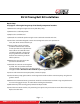
B5 S4 Timing Belt Kit Installation This tutorial takes you through a step-by-step procedure for installing a new timing belt and water pump on an Audi 2.7T in a 2001 B5 S4. Steps shown here also apply to 2.7T engines used in A6 and AllRoad models. This is a lengthy procedure. It requires above average repair skills and several professional automotive tools.
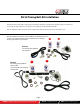
B5 S4 Timing Belt Kit Installation Tools we used: • • • • • • • • • • • • Schwaben camshaft/crankshaft locking tools - ES#2176242 Schwaben crankshaft locking pin - ES#4865 Schwaben ½” drive torque wrench - ES#2221244 Schwaben hex head driver set ES#11420 Schwaben Torx® driver set ES#11418 AirLift cooling system bleeder and refill tool angle head die grinder with abrasive disc metric socket set miscellaneous ratchets, extensions impact gun or large breaker bar for loosening crankshaft main bolt three-jaw p
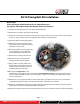
B5 S4 Timing Belt Kit Installation Our Audi B5 S4 comes to us with 106,000 miles on the odometer; the original timing belt, accessory belt, and water pump are still in place. (The recommended service interval is 105,000, so it’s time!) To expose the front of the engine so we can take photos, we remove the entire front end, including the lock carrier (front header) air conditioning condenser and fan, and radiator.
B5 S4 Timing Belt Kit Installation Repair Steps These steps begin with the front of the car removed for access. See pages 8-9 for engine images that identify component locations. 1) Remove the top engine beauty cover above the throttle body. 2) Remove the viscous fan clutch (left hand thread). 3) Loosen the air intake pressure pipe connection hose clamps. (These are the pressure ducts connecting the charge air coolers to the y-hose at the throttle inlet.) Remove the pressure pipes.
B5 S4 Timing Belt Kit Installation Repair Steps See pages 8-9 for engine image maps that identify component locations. 14) Remove the cooling fan support/accessory belt idler pulley. 15) Remove the crankshaft sprocket. 16) Replace the crankshaft seal. 17) Reinstall the crankshaft sprocket using the new crankshaft center bolt in the kit. 18) Install the camshaft locking tool. Loosen the retaining bolts at the cam sprockets 5-6 turns, but do not remove the bolts yet.
B5 S4 Timing Belt Kit Installation Repair Steps See pages 8-9 for engine image maps that identify component locations. 27) Install the new timing belt tensioning components (tensioner, tensioner roller, relay pivot). 28) Install the new timing belt. 29) Using an 8mm hex driver, turn the tensioner roller clockwise until the added belt tension compresses the belt tensioner piston far enough that the tensioner locking pin can be pulled out by hand.
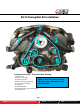
B5 S4 Timing Belt Kit Installation Component Locator - Accessory Belt Routing 1) throttle inlet 2) pressure pipe right Refer to this component map to 3) pressure pipe left identify major components and 4) power steering pump pulley 5) accessory belt tensioner their locations. 6) alternator 7) crankshaft pulley 8) idler pulley/viscous fan clutch mount 9) AC compressor Page - 8 Address: 1000 Seville Road, Wadsworth, OH 44281 Phone: 1.800.924.5172 Web: www.ecstuning.
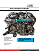
B5 S4 Timing Belt Kit Installation Component Locator 1) camshaft sprocket right 2) camshaft sprocket left 3) power steering pump 4) water pump 5) timing belt tensioner roller 6) tensioner relay lever (pivot) 7) tensioner 8) crankshaft sprocket 9) timing belt idler roller 10) dipstick tube Refer to this component map to identify major components and their locations. Page - 9 Address: 1000 Seville Road, Wadsworth, OH 44281 Phone: 1.800.924.5172 Web: www.ecstuning.
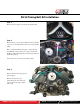
B5 S4 Timing Belt Kit Installation Step 1. Remove the top engine cover above the throttle inlet. Step 2. Remove the viscous fan clutch. The fan clutch assembly screws on to a threaded shaft on the accessory belt idler pulley. This is a left hand thread: to loosen it, rotate the fan nut clockwise using a 32mm (11/4”) open end wrench. Hold the pulley behind the fan nut stationary while you break the nut loose. Unscrew the viscous fan clutch and lay it aside. Step 3.
B5 S4 Timing Belt Kit Installation Step 4. Loosen the power steering pump bolts. (If you are doing it by hand without air tools, having the accessory belt in place helps hold it stationary as the bolts are cracked loose.) Step 5. Rotate the accessory belt tensioner hex with a 17mm socket and long handled ratchet to relax the belt tension. Peel the old accessory belt off the pulleys and discard it. Finish removing the power steering pump bolts loosened in the previous step.
B5 S4 Timing Belt Kit Installation Step 7. Unbolt and remove the hex socket accessory belt tensioner bolt (arrow). Remove the tensioner from the engine. FYI: Check the tensioner bearing for noise or looseness. The bearings in our old tensioner growled when we spun the roller. We recommend replacing the roller as part of this service to ensure that it will last as long as the new belt, and continue to apply the proper tension for maximum power transfer from the crankshaft to all accessory pulleys. Step 8.
B5 S4 Timing Belt Kit Installation Step 10. With the crank at TDC, make sure the larger holes in the cam alignment plates face toward the center of the engine. If not, rotate the crankshaft another complete turn until the TDC marks align again. Then fit the camshaft tool pins into the cam alignment plates. Step 11. With cam and crank marks aligned, install the crankshaft locking tool. Remove the plastic plug located in the side of the engine.
B5 S4 Timing Belt Kit Installation Step 13. Remove the vibration damper (main crank pulley) and the belt cover behind it to expose the crank sprocket and tensioner components. • • Remove the tensioner, pivot, and tensioner roller. Remove the timing belt. Step 14. Remove the accessory belt idler. Arrows indicate the bolt locations. Note that two of the bolt heads are accessed through slots in the pulley (upper arrows). With the accessory belt idler removed, go back and remove the timing belt idler.
B5 S4 Timing Belt Kit Installation Step 16. Pull the crankshaft sprocket off the crank snout by hand, and flip it over. Make sure the locator tab that indexes the sprocket to the crankshaft is not damaged (arrow). Improper installation of the sprocket has smashed the tab on some vehicles, so it pays to check it. Step 17. Remove the old crankshaft seal using a seal puller. Be careful not to damage the crankshaft or front engine case sealing surfaces. Step 18.
B5 S4 Timing Belt Kit Installation Step 19. Slide the crank sprocket back on to the crankshaft snout. Make sure the raised alignment tab inside the sprocket (Step 16) is properly engaged in the mating slot of the crank. With the sprocket properly aligned, hold it in place until the new crank bolt is screwed all the way down by hand. That way, the sprocket won’t shift out of location as the bolt is torqued. Step 20.
B5 S4 Timing Belt Kit Installation Step 22. Install a gear puller on the sprocket. (The puller shown here was originally designed for crank pulley removal on Chryslers, but does a great job here.) Many common gear pullers will do the job. Leave the loosened bolt in place. Use it as your press point. The pulleys are an interference fit on the cam snouts and will let go with a loud “pop” when they break loose. Step 23.
B5 S4 Timing Belt Kit Installation Step 25. Repeat the cam seal replacement process on the left bank camshaft. • • Remove the cam gear and rear timing cover. Remove the old cam seal, and install a new seal from the kit. Step 26. Reinstall the timing belt metal covers and sprockets on both camshafts. • • • Align the flat in the securing plate hole with the flat on the cam snout, as shown here (arrow). The larger hole in the cam plate should still face the center of the engine.
B5 S4 Timing Belt Kit Installation Step 28. Replace the water pump. Loosen and remove all the perimeter bolts, including the one hiding beneath the power steering pump (arrow). This is the reason we loosened the power steering pump way back in Step 6. Pry the pump away from its gasket. Have a drain pan ready to catch any coolant that escapes. Step 29. Clean away all old gasket material and dirt.
B5 S4 Timing Belt Kit Installation Step 31. Quality Control: Let’s pause and review. 1) Water pump installed? 2) Thermostat installed? 3) Cam seals installed? 4) Crankshaft seal installed and crank bolt tightened? Reinstall the three power steering pump bolts and tighten them (5), and reinstall the dipstick tube (6). Note: Replace the o-ring at the base of the dipstick tube if it is cracked or heat hardened. Page - 20 Address: 1000 Seville Road, Wadsworth, OH 44281 Phone: 1.800.924.5172 Web: www.
B5 S4 Timing Belt Kit Installation Step 32. Install the timing belt tensioning components on the front of the engine. All of these parts are included in your Ultra kit. Torque specs in parentheses. 1) tensioner (10 Nm) 2) tensioner relay (pivot arm) (20 Nm) 3) tensioner roller (20 Nm) 4) idler wheel (45 Nm) Quick notes: • We always apply a few drops of medium strength thread locker (blue) to all of these fasteners. • Do not pull the “grenade” pin from the tensioner yet. Step 33.
B5 S4 Timing Belt Kit Installation Step 35. Place the cam locking tool on the cam alignment plates. Route the timing belt around all sprockets. Make sure the belt teeth fully engage all mating teeth on all sprockets or the belt will not go on. If it will not go on easily, check that the belt and crank sprocket teeth are fully engaged. It is easy to get them “stacked,” tooth-to-tooth when the belt is first routed. Step 36. With the belt fully routed, adjust timing belt tension.
B5 S4 Timing Belt Kit Installation Step 38. With the cam locking tool installed, torque the cam retaining bolts to 55 Nm (40 ft-lb). Remove the cam locking fixture when both sprockets are tightened. Step 39. • • • Remove the cam locking tool. Remove the crankshaft locking tool and reinstall the timing hole plug removed in Step 11. Reinstall the lower timing cover. Step 40. Install the crankshaft pulley on the crank sprocket.
B5 S4 Timing Belt Kit Installation Step 41. Install the crankshaft pulley retainer bolts and torque them to 20 Nm. Step 42. Quality Control: Bar the engine over two complete revolutions (720°), returning to TDC. Using the cam locking tool and crankshaft pulley timing marks, double check camshaft/crankshaft timing. Remove the camshaft locking tool. • • Install the pulley on the power steering pump. Install the belt tensioner on the front of the block in the location indicated by the arrow.
B5 S4 Timing Belt Kit Installation Step 44. Make sure the tensioner boss and blind hole are aligned. Screw the mounting bolt to the block and torque it to 55 Nm (41 ft-lb). If your tensioner shipped with a locking pin (arrow), leave it in place until you route the accessory belt. See next page for accessory belt routing. Step 45. Forgetting how the accessory belt is routed is an easy thing to do. We include this image for your convenience. Step 46.
B5 S4 Timing Belt Kit Installation Step 47. Ready to button things up. Replace the front end components, including the lock carrier (header panel) radiator, condenser and condenser fan — anything removed to access the front of the engine. Fill the cooling system. We prefer using an AirLift cooling system vacuum test and refill tool. The AirLift has a cone shaped rubber snout that we insert into the coolant bottle fill neck, as shown. Step 48. Connect a shop air source to the tool and open the valve.
B5 S4 Timing Belt Kit Installation Coolant Mixing • • • Mix pure antifreeze with distilled or demineralized water for best results. Local water supplies, even from potable sources, may contain high concentrations of minerals that will collect and harden into heavy deposits inside the cooling system, restricting coolant flow. The ideal coolant for temperate climates is a 50/50 mixture of pure antifreeze and water that provides freeze protection to -34 degrees F.