
Operation Manual


GAIN
GAIN
CHANNEL 3 CHANNEL 4
IN
OUT
IN
OUT
GAIN
CHANNEL 1 CHANNEL 2
IN
OUT
GAIN
IN
OUT
NORMAL
BRIDGED
CHANNEL 1 & 2 BRIDGED CHANNEL 3 & 4 BRIDGED
220-240v~
100-120v~
CH3&4
CH1
CH3
CH4CH2
CH1&2
SERIAL No.
~50/60Hz
350W
e
f
g
h
GAIN
GAIN
CHANNEL 3 CHANNEL 4
IN
OUT
IN
OUT
GAIN
CHANNEL 1 CHANNEL 2
IN
OUT
GAIN
IN
OUT
NORMAL
BRIDGED
CHANNEL 1 & 2 BRIDGED CHANNEL 3 & 4 BRIDGED
220-240v~
100-120v~
CH3&4
CH1
CH3
CH4CH2
CH1&2
SERIAL No.
~50/60Hz
350W
a
b
c
d
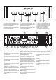
Fault conditions:
Under fault conditions such as short circuit, over-current (load impedance too low) and over temperature the level meter for the
affected channels will show no signal (white lights extinguished) and the red "0dB" LED will light indicating protection is
operating. All protection systems are auto-recovering (no latching of faults) so that normal operation resumes as soon as the
fault condition is removed.
Please note that the protection systems are shared in pairs, channels 1 & 2 are paired and channels 3 & 4 are paired. Hence
under a fault condition on channel 1, for example, both channels 1 & 2 will be shut down until the fault is cleared. Likewise, a
fault on channel 4 would result in channels 3 & 4 shutting down etc.
Limiter operation:
The amplifier has a separate limiter for each channel and this has been carefully balanced to provide protection against clipping
whilst still allowing the full output potential to be realised with music signals. Under conditions which would normally cause the
output to clip the limiter will automatically reduce the gain to prevent audible distortion. Some momentary clipping of music
transients will occur but this is generally inaudible and allows the perceived loudness to be greater than if all clipping were
strictly eliminated.
The limiter provides valuable protection for both the loudspeakers and the listener’s ears under overdrive conditions.
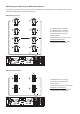
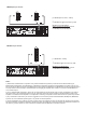
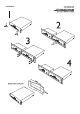
To bridge channels 1 & 2:
Note: only the channel 1 level meter will operate.
Channels 1 and 2 operate as independent channels with a 4 Ohm minimum load capability. In the "bridged" position channels 1
and 2 operate as a single high output channel with an 8 Ohm minimum load capability. See wiring diagram for connection
details.
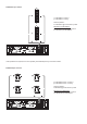
To bridge channels 3 & 4:
Note: Only the channel 3 level meter will operate.
a - Apply the input signal to channel 1 only.
Leave channel 2 input disconnected.
b - Connect the loudspeaker/s to the two
terminals as marked on the rear panel
(positive at very top and negative at very
bottom).
c - Set the mode switch for channels 1 & 2 to
bridged position.
d - Gain is adjusted with the channel 1 gain
control only (channel 2 gain control has no
effect)
e -Apply the input signal to channel 3 only. Leave
channel 4 input disconnected.
f - Connect the loudspeaker/s to the two
terminals as marked on the rear panel (positive
at very top and negative at very bottom).
g - Set the mode switch for channels 3 & 4 to
bridged position.
h - Gain is adjusted with the channel 3 gain
control only (channel 4 gain control has no
effect)
Bridge Mode