
Operation Manual

4
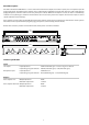
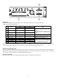
Rear Panel Connectors and Controls
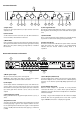
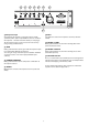
Front Panel Controls
a) Input Select
Choose one line input channel (1 to 6) to send to each zone
output (1 to 4).
b) Zone Volume
Set the volume level for each zone (1 to 4). Turn clockwise to
increase volume, anticlockwise to decrease.
c) Mic Volume
Four screwdriver controls set the volume level from the paging
microphone mixed with each zone’s music signal (zones 1 to 4).
When set to zero, music ducking (see Appendix 1) is disabled
for that zone.
d) Zone signal indicator
This white indicator LED illuminates when a signal is present.
The brightness of the LED gives some indication of the signal
level.
e) Power On/O
This is a true mechanical power switch (not a standby mode).
Its position is retained even during mains power failure.
f) Power on indicator
This blue indicator LED is o when the power switch is o and
lights blue when the mains power is on. Rapid ashing
indicates that the RS-232 enabled standby mode is in
operation.
a) Mains power input
IEC 3-pin connector. Use power cord supplied.
WARNING – The power cord must be connected to a power
socket outlet with a protective earth connection.
b) Line Inputs
Six line input channels on RCA phono pairs, each of which can
accept a mono or stereo source (stereo sources are internally
mixed down to mono). The front panel Input Select switches
(see above) pick which channel is to be sent to each Zone
output.
c) Line input gain controls
Rotary potentiometer to set gain for input channels 1, 2, 3, 4, 5
and 6.
d) Input level set aid
A single 2-colour LED is provided to assist setting the line input
levels. By applying a signal on each input in turn the level can
be set optimally. Green indicates the signal is in the optimum
range (>-20dB) and Red indicates that clipping is imminent
(>-2dB)
e) Zone Outputs (unbalanced)
Four mono RCA phono sockets carry the Zone (Line) outputs.
Each Zone Output can be selected to have a at frequency
response or the Audica speaker EQ (AEQ) equalisation (see
page 6 ).
f) Zone Outputs (balanced)
Balanced audio outputs are provided on 3-way Phoenix
connectors for Zones 1, 2, 3 and 4. These replicate RCA jack
outputs for each zone. The balanced output level is double the
unbalanced output.
If taking a single-ended output from the balanced output
terminals then use the ground pin for screen and ‘+’ pin for
signal. DO NOT connect the ‘–‘ output pin to ground.
b d f ec b dc b dc b dc
a
a
db e
c
f