
Operation Manual

5
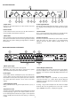
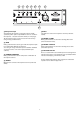
g) Microphone Input
An XLR balanced input for a paging microphone. A 48V
“phantom power” option is provided for active or condenser
microphones – selected via the DIL switch (see next page).
The microphone signal can be processed in various ways
using 6 rotary potentiometers.
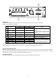
g1) GAIN
Rotary potentiometer sets the gain of the microphone input –
to accommodate dierent microphones.
Since the gain range on the Mic input is +50dB to -10dB this
can also be used as a line level input (maximum input
3.3Vrms).
g2) COMPRESSION RATIO
Rotary potentiometer sets the compressor contribution to
microphone channel.
g3) TREBLE
Mid-high tone control on microphone channel (centred at
5kHz).
g4) BASS
Low-mid tone control on microphone channel (centred at
150Hz).
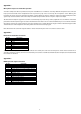
g5) DUCKER – FLOOR
Rotary potentiometer sets the music ducking “oor level”
(music attenuation level).
g6) DUCKER – RELEASE
Rotary potentiometer sets the music ducking release time
(music fade-up time).
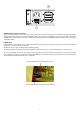
g7) MIC LEVEL SET AID
This is a 2-colour LED to assist in MIC input level setting. Green
indicates the signal is in the optimum range (>-20dB) and Red
indicates that clipping is imminent (>-2dB
[A more detailed description of the compressor and ducker
operation can be found in Appendix 1.
g1 g2 g3 g4 g5 g6 g
g7