
Operation Manual

6
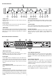
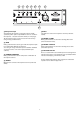
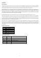
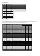
h) DIP switch
DIP switches are “ON” when down and “OFF” when up. The default setting is with all switches set OFF (up).
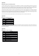
The table below describes their eect.
**In a system with only a single MULTIzone unit, if DIP switch 5 is set ON then any microphone signal will “duck” the music signal in
whichever zone(s) the microphone level is set above zero – but the microphone signal will not be heard.
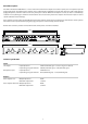
i) Remote Zone Controller inputs
Four RJ-45 sockets for connection to remote Zone Control wall plates. Connect via an 8-way CAT-5 cable terminated with RJ-45
plugs at each end for each Zone. The Zone Control wall plate takes over control of Zone input select and volume control – disabling
the front panel controls for that zone. See Appendix 2 for further details.
j) RS-232 control input
9-pin male “D-type” connector. See Appendix 4 for further details and the RS-232 control protocol.
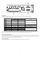
j
i h
SW Function
DIP switch UP
DIP switch DOWN
Notes
OFF
ON
1 RS-232 Address LSB 0 1
Use these switches to set the “unit number”
for RS-232 addressing. See Appendix 4 for
details.
Set all three switches to “0” (UP) to lock the
unit into Manual mode – disabling all RS-232
control.
2 RS-232 Address 0 2
3 RS-232 Address MSB 0 4
4
RS-232 source –
when unit is SLAVE
Unit is controlled from
local RS-232 socket
RS-232 control from
LOOP input
When unit is master, RS-232 signal is sent to
LOOP out – so DIP switch has no effect.
5
MIC source –
when unit is SLAVE
Local microphone “ducks”
unit’s Zone outputs
Master (LOOP) microphone
“ducks” unit’s Zone outputs
When unit is master, ducking signal is sent to
LOOP out – so DIP switch has no effect. **
6
Phantom Power
off
on
Phantom power to microphone
7
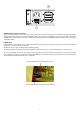
Zone 1 Audica EQ
off
AEQ
Audica speaker EQ
is designed to optimise
performance from Audica Pro loudspeakers.
If Audica Speaker EQ is to be used in a system
with a subwoofer, please refer to Appendix 5.
8
Zone 2 Audica EQ off AEQ
9
Zone 3 Audica EQ
off
AEQ
10
Zone 4 Audica EQ
off
AEQ