Owner’s Manual
Audient Limited, Hampshire, England, RG25 2PL Telephone: +44 (0) 1256 381944 www.audient.com V 1.
Introduction How to use this manual Unpacking 5 Service and Repair 6 Ventilation 6 Power-up 6 Audio interfaces 7 Dimensions 7 Specifications 8 Contents 4 Overview Console layout 10 In-line architecture 11 Solo 13 Metering 13 Typical configuration Glossary 15 16 Console functions.
Introduction. Thank you for selecting this Audient product. We hope that your new ASP4816 console will provide an intuitive, ergonomic and tactile path to analogue enlightenment. ASP4816 is a small format analogue console with a big heart. Small in stature, yet not in functionality, it provides an impressive array of connectivity, signal conditioning, routing, summing, processing and monitoring capability in one beautiful, tidy package.
Introduction. Unpacking Your Audient ASP4816 Console has been carefully and meticulously tested and inspected before dispatch. Please check for any signs of transit damage. If any signs of mishandling are found please notify the carrier and inform your dealer immediately. The packaging should include the console, an IEC power cord and this manual.
Introduction. Service and Repair The console uses a complex internal pcb sandwich arrangement making field service only possible by a qualified technician. If any technical issues do arise with your console, please contact your dealer as soon as possible to arrange for technical support. Do not attempt to fix the console unless qualified to do so. See the warranty section provided at the end of this manual for details of your cover.
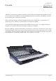
Introduction. Audio interfaces The ASP4816 has been designed and developed to provide highly robust system integration interfaces, allowing worry-free system hook-up under the most demanding situations. Inputs and outputs are implemented using advanced electronically balanced or ground sensing topologies and are fitted with extensive RFI rejection networks. All signal interfaces are also fully protected against accidental misuse e.g. by the connection of phantom powered cables.
Specifications Frequency Response Mic input to Mix output Line input to Mix output <+0,-0.3dB <+0,-0.3dB 20Hz-20kHz @6-40dB gain. 20Hz-20kHz @0dB gain. THD AND NOISE AT +20dB OUTPUT Mic XLR input to any output Line input to any output Tape input to any output <0.005% at 1kHz <0.005% at 1kHz < 0.003% at 1kHz NOISE Mic EIN (20-20kHz, 150R source) Bus noise (no inputs routed) Bus noise (36 inputs routed) <-127.
Overview ASP4816’s many features include 16 channels of Class-A discrete microphone preamplifiers as used in our world renowned ASP8024 console and ASP008 8-channel microphone preamplifier, guaranteeing outstanding sonic transparency and detail. When combined with high resolution bargraph metering, input conditioning, comprehensive cue monitoring options, ASP4816 is right at home in a tracking environment.
Overview Console layout © Audient Ltd Page -10-
Overview In-line architecture ASP4816 has an In-line architecture. This means that the ‘channel path’ and the ‘monitor path’ are both included in the same physical strip. Because the two signal paths are integrated in this way, in-line consoles have sometimes been seen as confusing. However great care has been taken in the cosmetic and ergonomic design of the ASP4816 to make the two paths easily distinguishable from one another.
Overview © Audient Ltd Page -12-
Overview Solo Pressing a solo button on a channel with either PFL or AFL selected allows either the PFL or AFL signal for that channel to be heard on the monitors and viewed on the stereo output meters. Associated with the solo switch is the SOLO-IN-FRONT control and this allows the relative level of the solo’d signal and the stereo mix to be adjusted. It is therefore possible to hear a channel in isolation or with some amount of the mix behind it.
Overview Metering - continued 0VU is calibrated to a nominal operating level of +4dBu. Which in turn is relative to a typical EBU calibration of +18dBu = 0 dBFS. 0 dBFS is your absolute maximum digital level (full scale) and should be avoided at all costs - digital clipping is not a pleasant sound. As such the bargraph meter scale on ASP4816 is calibrated in dBFS, such that +4 dBu = 0VU = -14 dBFS.
Typical configuration © Audient Ltd Page -15-
Glossary AFL This allows after fade (post fade) signals to be heard on the monitors and viewed on the main stereo meters. Auxiliaries Sometimes known as auxiliary sends these are used as secondary mix buses. The mixes created on these buses are then used to feed effect units or are fed back to the performers as a Foldback feed. Every channel has access to the auxiliary mixes and the contribution of any channel can be varied by using the appropriate auxiliary level control.
Glossary Flip Flip allows the inputs to the signal paths to be swapped. Normally the LF path will carry the DAW input, however, with FLIP pressed it will carry the MIC/LINE input while the DAW input will travel through the SF path. Foldback Foldback is a mix that is returned to the performers in the studio in order that they can play in time with what is already recorded.
Glossary Pan Short for panoramic potentiometer this control places a mono source signal onto the stereo bus. The proportion of signal fed to the left and right buses is variable (using the pan control) and alters the spatial position of an instrument within the mix. Thus a number of channels can all be panned to different spatial positions.
Console functions.
Console functions. Channel Strip INPUT POD The input pod is the gateway to the remainder of the signal processing of the console. There are three inputs, a mutually exclusive microphone and line input, and a tape input. Note the different colouring used to identify the different signal paths of the pod. Anything on a light background is associated with the LF path while anything on a dark background is associated with the SF path.
Console functions. Channel Strip ROUTING and AUXILIARIES The routing section takes the signal from the SF path and routes it to the bus outputs which in turn are usually connected to the inputs of a DAW or other recording device. Buses 1 to 8 also have a parallel path and feed the 8 sub-groups. These can be used to pre mix channels together for final mix down or as sends to a DAW or other recording device. There are 16 bus outputs accessed by 8 routing buttons and a SHIFT button.
Console functions. Channel Strip EQUALISER Note the dark background indicating that the equaliser is normally associated with the LF signal path. The equaliser is split into two sections - one for high and low frequencies (HF/LF) and the other for middle frequencies (MIDS). Both sections can be switched in and out independently and switched into the SF signal path independently. The HF section has a boost/cut range of 15dB.
Console functions. Channel Strip SHORT FADER (SF) There are 3 back illuminated indicators showing the selected input to the SF path. This can be changed between Mic/Line and DAW using the FLIP switch. LF Source allows the source for the SF path to be taken from the LF path. This could be used during mixdown to send the LF signal through the SF path up to the routing matrix where the bus outputs can be used as additional effect sends.
Console functions. Channel Strip FLIP and PAN The FLIP switch allows the MIC/ LINE input and the DAW input to be reversed. Normally the DAW input feeds the LF signal path - with FLIP pressed it will feed the SF signal path. The MIC/LINE input normally feeds the SF signal path and with FLIP pressed it will feed the LF signal path. Illuminated indicators in each section show which input is selected to the LF and SF paths.
Console functions. Channel Strip LONG FADER (LF) Located close to the operator this fader operates on the LF signal path and is therefore mainly used for creating the monitor mix and the final stereo mix for the title. The fader is expected to operate around the 0dB mark with 10dB of gain in hand allowing the signal to be increased or decreased in level. When level setting start with the fader in this position then adjust the input sensitivity control for the correct level to optimise the gain structure.
Console functions. Channel Strip INPUT CONNECTORS The rear mounted connector panel is where the input, output and insert point connectors are located. The microphone input uses an XLR connector while the line input, DAW input and the insert sends and returns use Tip, Ring and Sleeve jacks. 1 MICROPHONE INPUT. Microphones or other low levels inputs can be connected to this input. 2 LINE INPUT. This input can be selected in place of the microphone input.
Console functions. Masters STUDIO SPEAKERS and FOLDBACK This section of the master module looks after the STUDIO LOUDSPEAKER and FOLDBACK outputs of the console. In every case the same sources are available EXT 1 EXT 2 CONTROL ROOM (C/RM) AUXILIARY A (AUX A) AUXILIARY B (AUX B) EXT 1 and 2 are external inputs to the console and could be anything you care to plug in. C/RM selects the control room monitor output as the source.
Console functions. Masters CONTROL ROOM MONITORING The Control Room Monitoring system is one of the most used systems in a studio. Typically there are several sets of loudspeakers with a main pair and one or more alternate pairs. These are sometimes referred to as Near, Far and Mid field monitors depending on their proximity to the listening position. The ASP4816 provides for 4 pairs of loudspeakers, a MAIN pair and ALTERNATE 1, 2 and 3. Source selection is made from either the MIX or DAW, EXT 1 and 2.
Console functions. Masters OSCILLATOR The 4 frequency oscillator can be assigned either to buses 1-16 or to the stereo mix bus. The level is adjustable and when not in use the oscillator should be completely turned off. SOLO This is the master control area for the AFL/PFL and SOLO IN PLACE system. If SIP is not illuminated then the console will be in either AFL or PFL mode depending upon the PFL/AFL switch.
Console functions. Masters COMPRESSOR A compressor can be switched into the main stereo signal path when required. Note that it is located after the mix insert point but before the main fader. The compressor characteristics are optimised for use in mix processing while many of the parameters remain under the control of the engineer. Threshold, Gain Make Up, Attack, Release and Ratio are all adjustable while the entire processor can be switched out of circuit when not required.
Console functions. Masters Typical compressor settings.
Console functions. Masters STEREO INPUTS © Audient Ltd 1 ROUTING SWITCHES allowing the input signal to be sent to the DAW or other recording device. 2 SHIFT button working with the routing switches to give access to tracks 9-16. 3 F/B A allows the input signal to be fed to Foldback A. 4 F/B B allows the input signal to be fed to Foldback B. 5 TRIM control to compensate for different input levels. This has a range of ±20dB.
Console functions. Masters LINE I/Ps 17-14 and SUB-GRP OUTPUTS. 1 The PAN knob pans the subgroup signal across the stereo bus. 2 MIX allows the sub-group to be assigned to the stereo mix bus and hence the main console output. 3 SOLO allows the sub-group signal to be auditioned depending upon the selected pan mode. 4 CUT mutes the sub-group output. In addition to routing signal to the bus outputs for recording, the first eight buses are also fed to 8 subgroup outputs.
Console functions. Masters TALKBACK Talkback is used to communicate with the STUDIO, the FOLDBACK system or the Bus outputs of the console. Note that the talkback to the foldback system will work even when the foldback levels are turned down. The talkback microphone may be phantom powered by connecting Link 1 on the PC10801 board. 1 The LEVEL control adjusts the talkback level. 2 Pressing SLATE allows talkback to the bus outputs. This allows track identification information, for example, to be recorded.
Console functions. Masters AUX MASTERS 1 A U X I L I A RY M A S T E R LEVEL controls the overall auxiliary output. 2 SOLO button used to audition the auxiliary output. This is always AFL. 3 The LINK button is used when it is required to combine signals from different auxiliaries into a common signal. The leftmost auxiliary becomes the overall master, thus if auxiliary 3 is linked to auxiliary 1 then the output of auxiliary 1 should be used as the master output.
Console functions. Masters BUS MASTER TRIM 1 © Audient Ltd BUS MASTER TRIM controls the overall level of a bus output. The BUS MASER TRIMS are the final stage of level control over the signals routed to the bus outputs. Each bus output has a trim with a range of ±10dB.
Console functions. Masters MASTER FADER The master fader is used to control the stereo output of the console. Unlike the channel faders it is calibrated with the 0dB mark at the top as the main purpose of this fader is to create a fade out at the end of a title. Under normal operating conditions the fader should always be set at maximum. If it has to be pulled back a significant distance it indicates that the levels to the mix bus are too high and should be reduced.
Console functions. Masters © Audient Ltd CONTROL ROOM CONNECTORS 1 MAIN Control room loudspeaker output. 2 ALTERNATIVE 1 loudspeaker Output. 3 ALTERNATIVE 2 loudspeaker Output. 4 ALTERNATIVE 3 loudspeaker These are the connectors for the control room loudspeakers. There is a main output and 3 alternative outputs which can be selected from the control surface of the console. Each output is stereo, having a left and right connector.
Console functions. Masters 1 STUDIO LOUDSPEAKER . These carry the outputs to the studio loudspeaker system. The output depends upon the selection made on the control surface of the console. 2 FOLDBACK A output. Foldback is normally used as a feed to headphones. The output depends upon the selection made on the control surface of the console. © Audient Ltd STUDIO/ FOLDBACK CONNECTORS 3 FOLDBACK B output. Foldback is normally used as a feed to headphones.
Console functions. Masters AUX CONNECTORS Not all of the ouputs are shown for clarity. © Audient Ltd 1 CUE A and CUE B outputs. These auxiliaries are normally used as feeds to the foldback system by selecting them on the control surface of the console. They can also be used as additional effects sends. 2 AUXILIARY 1 and 2 outputs. The remaining auxiliary outputs are identical. The auxiliary outputs are typically used to send to effect units such as reverberation units.
Console functions. Masters SUB-GRP INSERT/ LINE INPUT 17-24 CONNECTORS This panel carries the connectors for the sub-group insert points. There are 8 sub-groups and each insert point has a send output and a return input. Signal is always present on the send output. If required the insert returns could be used as very basic inputs to the stereo mix bus during mixdown, from a submixer or sampler etc. The insert return jacks can also be used to provide 8 additional line inputs to the mix.
Console functions. Masters STEREO INPUT CONNECTORS This panel carries the input TRS jacks for the stereo inputs located on the master section of the console. There are 4 returns each with a left and a right input. If a mono source is used then it should be plugged into the left input. This is normalled over to the right input causing the signal to travel through the left and right signal paths of the return. If a plug is inserted into the right input the normalled connection is broken.
Console functions. Masters MONITOR INPUTS This panel carries the connectors for the external inputs to the monitoring system. All three inputs are available as sources to the control room monitoring system while the first two can be used as sources for the studio monitoring system and the foldback system. 1 Input for DAW 2 Input for EXT 1 3. Input for EXT 2.
Console functions. Masters MIX OUTPUTS There are 3 sets of stereo output connectors enabling the connection of 3 stereo recording machines. The outputs can be used for many purposes of course. Associated with the outputs are the mix insert points. They allow a final mix processor to be inserted into the MIX path, and are located before the MIX compressor/ limiter. 1 MIX INSERT SEND jacks. There is a separate send output for the left and right mix. 2 MIX INSERT RETURN jacks.
Console functions. Masters BUS, SUB-GROUP/ LINE 17-24 OUTPUT CONNECTORS Rather than having individual connectors for each bus and subgroup output it is much more convenient (and quicker to make a connection) if they are on D-sub multi-pole connectors. © Audient Ltd 1 SUB-GROUP/LINE 17-24 OUTPUT CONNECTOR 2 CONNECTOR for BUS outputs 1 through 8. 3 CONNECTOR for BUS outputs 9 through 16. The bus sends are split across 2 connectors with each carrying the bus outputs for 8 tracks.
Console functions. Masters THE MASTER METERS Metering has been addressed on the input modules although there are also meters associated with the master functions on the console. The output meters show the output levels of the sub-groups and also the stereo output. If problems are indicated here with the level being either too high or low then it is most likely that the problem is further back in the signal path. Follow our procedure for gain setting to see if this remedies the situation.
Console functions. Masters THE Sub-group/ LINE INPUT 17-24 METERS There 8 sub-group outputs meters on the console (only 2 have been shown for clarity). The sub-groups are accessed in parallel with the main bus outputs and only the first 8 buses therefore have a corresponding sub-group. The sub-groups are able to feed the stereo mix and also have their own outputs located on the rear panel of the console. The sub-group outputs can be directly used to feed a DAW or other recording device.
Block diagrams © Audient Ltd Page -48-
© Audient Ltd Page -49-
© Audient Ltd Page -50-
© Audient Ltd Page -51-
Warranty. Your ASP4816 comes with a manufacturer’s warranty for one year from the date of despatch to the end user. The warranty covers faults due to defective materials used in manufacture and faulty workmanship only. During this warranty period Audient will repair or at its discretion replace the faulty unit provided it is returned carriage paid to an authorised Audient service centre.