operation manual M O N IT O R S T ER EO M O N IT O R SO U R E C O R D S FO R M A T SU B O U R C E G U ID E R CE E D NC E O C D O E D R E / R V O LU M E M O 0 1 0 D E
Contents UNPACKING .............................................................................................................. 4 IMPORTANT SAFETY INSTRUCTIONS ....................................................................... 4 MAINS POWER SUPPLY ............................................................................................ 4 VOLTAGES ................................................................................................................ 4 FUSES ................................
Operation Manual Introduction Thank you for selecting an ASP500 Series controller for your application. We have designed this equipment to provide you with the best possible tool to deal with todays demanding requirements. We have taken a great deal of pride and care in the manufacture of this equipment so that it will provide consistent and reliable performance. Please take a little time to study the contents of this manual so that you can be sure of getting the best performance from this equipment.
Operation Manual Installation UNPACKING Your ASP500 Series Controller has been carefully and meticulously tested and inspected before despatch. Please check for any signs of transit damage. If any signs of mishandling are found please notify the carrier and your dealer immediately. Your ASP500 Series Controller packing should contain an ASP510 Surround Processor rack unit, an ASP510 Remote Control, a mains power cord, and a CAT5 interconnecting cable, along with this manual.
Operation Manual Installation AUDIO INTERFACES The ASP510 Controller has been designed and developed to provide highly robust system integration interfaces, allowing worry-free system hook-up under the most demanding situations. In order to maintain optimum EMC performance it is important that screens are properly connected at both ends of cable runs. In this way the electromagnetic shield provided by the equipment chassis and the cable screens will be optimised to reject interference.
©audient 5/2001 ELECTRONICALLY BALANCED FEMALE D-SUB LFE LEFT SURROUND RIGHT SURROUND ELECTRONICALLY BALANCED FEMALE D-SUB LEFT RIGHT CENTRE LFE LEFT SURROUND RIGHT SURROUND NOT USED NOT USED TYPE SIGNAL NUMBER 1 2 3 4 5 6 7 8 NOT USED NOT USED CENTRE RIGHT ENCODED INPUT LEFT (Lt) ENCODED INPUT RIGHT (Rt) ENCODED OUTPUT LEFT (Lt) ENCODED OUTPUT RIGHT (Rt) STEREO BUS LEFT STEREO BUS RIGHT LEFT SURROUND LFE CENTRE RIGHT RIGHT ALTERNATE LEFT ALTERNATE RIGHT SURROUND LEFT S
Operation Manual Installation CONTROL INTERFACES The ASP510 allows various logic control signals from the host mixing console to be interfaced to allow continued operation of console solos etc. These connections are detailed on the next page and are made via AC/DC floating opto-isolators that will successfully detect any positive or negative going control voltage between 2v and 24v.
Operation Manual Installation CONFIGURING YOUR INSTALLATION OVERVIEW The ASP510 has been designed to allow maximum f l ex i b i l i t y in system configuration without compromising either ease of installation or use. It is important to recognise that the ASP510 can provide comprehensive management of both monitoring and record functions in a Surround environment.
Operation Manual Application notes FUNCTIONS AND CONTROLS ©audient 5/2001 9
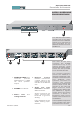
Operation Manual Functions & Controls ASP510 SURROUND PROCESSOR RACK 0 SUR RO UN D SOUND CON TR OL L ER -1 0 0 +1 0 -1 0 0 +1 0 -1 0 0 +1 0 -1 0 0 +1 0 -1 0 0 +1 0 -1 0 +1 0 1 2 The Surround Processor contains all of the audio electronics for the ASP510 system. It is connected to and controlled by the ASP510 remote unit via an RS485 link. 3 4 5 1. MONITOR LEVEL trim controls provide adjustment of +/- 10dB for each s p e a ke r output. 4.
Operation Manual Functions & Controls ASP510 REMOTE CONTROL FORMAT SELECTION 1 2 MONITOR FOR MAT 3 GUI DE MODE IS OL AT E VOLUME STEREO RE COR D SOURC E BUS E NC O/P ENCODER/ DECODER STE REO MONITOR SOURCE SURROUND SURROUND SURROUND CO CONT NTROLL ROLLER ER 1. MONITOR FORMAT is selected using these five switches. An illuminated legend displays the selected choice from 5.1, LCRS, Stereo, Mono and Bypass.
Operation Manual Functions & Controls ASP510 REMOTE CONTROL SPEAKER CONTROL 4 MONITOR FORMAT GUI DE MODE IS OL ATE VOLUM E STEREO RECORD SO URCE BUS E N C O/P 5 ENCODER/ DECODER STE RE O MONITOR SOURCE SURROUND SURROUND SURROUND CONTRO CONTROLLER LLER 4/5.MODE sets the six i l l u m i n a t e d s p e a ke r switches to act in either ISOLATE or CUT mode. An illuminated legend shows which mode is active.
Operation Manual Functions & Controls ASP510 REMOTE CONTROL SOURCE SELECTION MONITOR FOR MAT GUIDE MODE IS OLATE VOLUME STEREO RECORD SOURCE BUS 12 EN C O/P ENCODE R/ DECODE R STEREO MONITOR SOUR CE 11 SURROUND SU SURRRO ROU UN ND D CCO ON NTR TRO OLLE LLERR 10. The Encoder/Decoder are inserted into the monitor chain using the IN switch. 11/12. Three Stereo and three Surround MONITOR SOURCES are provided. REC selects the direct bus signal from the console or DAW.
Operation Manual Functions & Controls ASP510 REMOTE CONTROL SOURCE SELECTION 14 MONITOR FORMAT GUI DE MODE IS OL AT E VOLUME STEREO RE COR D SOURC E 13 BUS E NC O/P ENCODER/ DECODER STE REO MONITOR SOURCE SURROUND SU SUR RR RO OU UN ND D CO CO N NTR TRO OLL LLEER R 13. T h e s o u r c e f o r t h e STEREO RECORDERs can be selected as the Stereo BUS feed from the console or DAW, a DOWNMIX of the Direct Surround source or the LtRt output of the ENCODER.
Operation Manual Specifications SPECIFICATIONS LEVELS Nominal levels +4dBu Maximum input +24dBu Maximum output +24dBu FREQUENCY RESPONSE Any input to any output +/-0.25dB 22Hz -22kHz THD AND NOISE Any input to any output <0.003% @+4dBu, 1kHz At speaker outputs <-92dBu 22Hz - 22kHz (Source/source) >80dB 1kHz NOISE CROSSTALK CHANNEL TRACKING +/-0.25dB 0 to-24dB SYSTEM INTERFACES 25pin D-type females for: 25pin D-type males for: 5.1 Surround play A and B 5.
Operation Manual Warranty WARRANTY Your ASP500 series Controller comes with a manufacturer s warranty for one year from the date of despatch to the end user. The warranty covers faults due to defective materials used in manufacture and faulty workmanship only. During this warranty period Audient will repair or at its discretion replace the faulty unit provided it is returned carriage paid to an authorised Audient service centre.
S URROUN D PLAY B S URROUN D PLAY A SURROUN D A ND ST EREO BU S IN PUT S ST EREO RECORD / PLAY STEREO RECORD SOURCE SURROUND MONITOR SOURCE S URROUND PLAY B S URROUND PLAY A A ENCOD ER OU TP UT STE REO MIX D OW NMIX SURROU ND REC REC PLAY B PLAY A ENCOD ER D ECODER B PINK NOIS E S URROUN D RECORD PINK ENCODER/DECODER INSERTION Rt Lt A NY ST EREO SOU RCE STEREO MONITOR SOURCES IN DOWNM IX ST EREO MONITOR FORMAT LCRS 80H z FILTER IN SOLO SOLO D C SEN SE MONO CU T REF D IM
Operation Manual Application notes APPLICATION NOTES ©audient 5/2001 18