
User guide


Operation Manual
Installation
5
©audient 5/2001
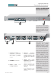
SIG NAL
N U M B ER
+V E
SIG NAL
-V E
SIG NAL
SC R EEN
D - SU B P IN
1 241225
2 102311
321922
47208
518619
64175
715316
81142
N o te
: A ll und e sig na te d pins a re
unco nnected . A ll sc re en conne cti on s a re
jo in ed in s id e th e unit and c onnec ted to
m eta lw ork ea rth .
AUDIO INTERFACES
The ASP510 Controller has been designed
and developed to provide highly robust
system integration interfaces, allowing
worry-free system hook-up under the most
demanding situations.
Inputs and outputs are implemented using
advanced electronically balanced or ground
sensing topologies and are fitted with
extensive RFI rejection networks.
In this way the electromagnetic shield
provided by the equipment chassis and
the cable screens will be optimised to
reject interference. It is recommended that
only high quality braided screen cables
are used to avoid compromising EMC
performance.
PIN CONVENTIONS
Signal interfaces are provided on 25 pin D
Sub type connectors with 4-40 screw
thread jack posts. Wiring is in accordance
with the DA88 convention. Pin allocations
are shown in detail on the next page.
Important : When preparing your D-SUB
interface cables please note that the
maximum shell size that can be
accommodated is 18 x 60mm.
In order to maintain optimum EMC
performance it is important that screens
are properly connected at both ends of
cable runs.
To unbalance the outputs of the ASP510
the -ve Pin should be connected to its
adjacent 0v pin at the output of the ASP510
Surround Processing rack unit. Similarly,
inputs from unbalanced sources should be
connected via twin screened cables with
the -ve Pin connection tied to the screen at
the unbalanced source.
+
+
+
+
PIN 1
PIN 13
1
2
4
6
3
7
5
8
WIRING SIDE OF FREE MALE CONNECTOR
+
+
+
+
1
3
7
5
4
2
6
8
PIN 13
PIN 1
WIRING SIDE OF FREE FEMALE CONNECTOR