AUTOMATION & CONTROL SURFACE MANUAL Version: 1.
Contents ASP2802 Fader Automation........................................ Page 3 Automation Overview Automation Setup Automation Modes Writing, Viewing & Editing Automation Automation Safe 4 5 9 10 12 ASP2802 Control Surface Setup................................. Page 13 Control Surface Panel Overview Control Surface Setup Running Automation & Control Surface Simultaneously 14 15 18 ASP2802 Control Surface Functions...................
Fader Automation
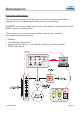
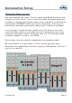
Automation Overview of Functions The diagram below provides an overview of the automation system and the parameters that can be controlled. ASP2802 provides fader and mute automation along side its full DAW control surface layer.
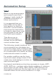
Automation Setup Assuming that you have followed all steps outlined in the main manual networking section for Apple Mac (page 84 onwards), you will have connected ASP2802 to your studio computer and connected to the console via AuNet.
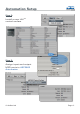
Automation Setup Step 2: Install a new HUITM control surface Step 3: Assign input and output MIDI ports to ASP2802 Automation © Audient Ltd Page -6-
Automation Setup Step 4: Lock the channel strip view mode to Tracks Only Step 5: Close the control surface setup window (top left) and navigate to: Logic Pro > Preferences > Control Surfaces > Preferences... Here set the following parameters to ensure smooth operation: a.) Please set the resolution of relative controls to 1024 (or any value greater than 512) b.) Please set the maximum MIDI bandwidth to 100% c.
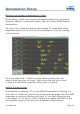
Automation Setup Step 6: Return to the arrange page and create 8 new mono “dummy” audio tracks for ASP2802 automation to follow and write to. It is suggested that you place them at the start of your session so that the first HUITM control surface that drives the automation is locked in place here, note the grey bars to the left of the first 8 track headers. This allows you to add a second HUITM surface for the ASP2802 control surface layer.
Automation Setup Automation Modes in Logic We recommend the use of Touch, Latch and Read mode for the majority of your work. Touch mode provides the most essential workflow, writing automation data when a fader is touched and moved (the ASP2802 faders are touch sensitive), returning to previously recorded automation data when a fader is released. Latch mode is useful but be careful as it will latch to the last touched fader position until play/record is stopped so you may overwrite important rides.
Automation Setup Writing and Viewing Automation in Logic Once setup, rides and mutes can be recorded into Logic and viewed, edited or manually drawn like any other DAW based automation. To view your recorded automation press ‘A’ (standard Logic keyboard shortcut) or click on the automation icon at the top of the screen. You may also find it useful to hide these tracks with the useful hide function in Logic. Note that this will only work if step 4 is followed (channel strip view to tracks).
Automation Setup Hiding Tracks in Logic cont. Please note that Logic is currently the only platform that will happily allow two HUITM control surfaces to be active and independent at this point. Therefore in Logic it is quite possible for you to sit permanently in the DAW layer when mixing and use the ASP2802 control surface to ride the analogue fader automation. Just treat the ASP2802 fader and mute automation channels like any other channel in your DAW mix.
Automation Enable / Safe A Note on Automation Safe Automation safe should be used when you want to isolate a particular channel from automation - for example - to audition rides without “fighting” existing automation data or without “printing” the rides if channels are still in write enabled. When the console boots automation safe is engaged by default.
Control Surface Setup
Control Surface Panel Control Surface Operation The control surface panel on ASP2802 provides access to many common and useful DAW functions. Please follow the setup procedure outlined on pages 15 to 18 and then read onwards from page 19 to learn how to operate the ASP2802 control surface.
Control Surface Setup Assuming that you have followed all steps outlined in the networking section, you will have connected ASP2802 to your studio computer and connected to the console via AuNet.
Control Surface Setup Step 2: Install a new HUITM control surface (a 2nd if using one for the fader automation). If using two HUITM controllers (one for automation and one for control surface), please ensure that they are dragged apart so that they can exist as two independent controllers. Step 3: Assign input and output MIDI ports to ASP2802 Control Surface.
Control Surface Setup Step 4: Close the control surface setup window (top left) and navigate to: Logic Pro > Preferences > Control Surfaces > Preferences... Here set the following parameters to ensure smooth operation: a.) Please set the resolution of relative controls to 1024 (or any value greater than 512) b.) Please set the maximum MIDI bandwidth to 100% c.
Control Surface Setup Running Automation & Control Surfaces Simultaneously Please ensure that there are two banks of 8 channel controllers indicated in the track-header if using two HUITM instances to make the most of ASP2802’s powerful fader automation and DAW layer. The first 8 channels should be fixed to the console automation and permanently highlighted at the start of your Logic session.
Control Surface Functions
Control Surface Functions Entering DAW Layer To enter the DAW layer for control surface functionality ensure that the DAW switch (1) is depressed and illuminated. Whenever it is not illuminated, the faders and channel switches operate in the analogue layer. However, some of the control surface functionality remains active when in the analogue layer to aid your session workflow, allowing simultaneous control of both analogue fader level and important DAW functions.
Control Surface Functions Editing Setup Parameters To edit parameters in any of the OLED displays when in setup mode, rotate the corresponding rotary encoder to change values and then press the setup switch to select and apply the changes. Note that once a change has been made, the setup switch LED will flash to indicate that a setting has changed and will return to a solid red once changes are confirmed.
Control Surface Functions Console Setup Switch Setup Page 3 - IP Address (networking option) Setup Page 4 - Subnet Mask (networking option) Setup Page 5 - Port (default 1212, networking option) Setup Page 6 - Firmware Info © Audient Ltd Page -22-
Control Surface Functions Transport Panel The transport panel on ASP2802 provides access to the following functions: • • • • • Rewind (3) Fast-Forward (4) Stop (5) Play (6) Record (7) A jog wheel (8) is also provided and can be used to control several DAW commands. When operating the rewind or fast-forward controls (3 & 4) it should be noted that one switch press initiates the command, and further switch presses will increase the speed of the playhead rewind or fast-forward.
Control Surface Functions Transport Panel cont. By using the scrub function (12) in conjunction with the jog wheel (8), the playhead cursor can be used to ‘scrub’ through the audio within your Logic session in realtime as if ‘rocking the tape against the playhead’. This is useful for finding edit points and punch-in locations etc. When in this mode, the scrub switch will be illuminated in solid green.
Control Surface Functions Navigation & Utility Controls cont. The marker control (10) can be used to add markers to the global marker track in Logic. This may be useful for flagging edit points during a take for example. Tap on the marker switch to place a marker in the timeline, multiple taps place multiple markers at their corresponding timeline positions. The nudge control (11) is currently unsupported in the initial Logic software release. Please see www.audient.
Control Surface Functions Navigation & Utility Controls cont. Track Select Mode Region Select Mode Vertical Zoom Mode Horizontal Zoom Mode Track Navigation Controls In order to navigate around your session and bring banks of 8 tracks onto the ASP2802 control surface, there are several switches that are useful. The bank switches (15) allow you to ‘bank’ in eight channel blocks left and right, through either your tracks or arrange page channels (for example 1-8 or 9-16).
Control Surface Functions Track Navigation Controls cont. To access encoder parameters and / or OLED display information for all eight channels, the 5-8 switch (16) must be used to access the last four channels in the bank of eight. The channels that are active and available on the encoders are illuminated in blue. The encoders can be used to access pan, aux, insert and input / output assigns for the four active channels.
Control Surface Functions DAW Meters If you wish to display eight channels of DAW metering on ASP2802’s LED bargraph meters, a global command switch (17) DAW Meters, provides this functionality.
Control Surface Functions Channel Select Mode The select mode panel provides various functions, some of which operate on the analogue layer and are useful for automation control (auto safe etc), while others are specifically used for control over DAW functions on the DAW layer. Above each fader are three illuminated push switches.
Control Surface Functions Record Enable Mode Use record enable (20) within DAW control surface mode when arming tracks for recording in Logic. Activate this mode and then use the large green channel select switches (18) to record enable each track active on the eight channel HUITM bank. Please note that by using multiple channel select switches (18), you can record enable more than one track at once.
Control Surface Functions Automation Modes cont. To access the automation mode selections using the ASP2802 control surface press the automation mode switch (21). Observing the OLED displays, you should see a series of options appear above each encoder. You can page to the right using the page switches (26) to access the next set of options (trim and off). Please note that trim does not function in Logic (Pro Tools only) so off is the only functioning option on page two.
Control Surface Functions Group Mode To access Logic’s internal grouping function press the group mode switch (22) in the select panel. If this is your first group to be created in Logic, pressing a channel select switch (18) to add a channel to the first group will bring up the Logic group settings dialogue box. Here you can set parameters for the group (via the mouse) such as linking record enable state or channel strip colour etc.
Control Surface Functions Group Mode cont. Unfortunately due to the restriction of the HUITM protocol there is no visual feedback relayed to the ASP2802 OLED displays from Logic as to which group is selected for editing. Therefore a careful eye must be kept on Logic to see which tracks end up in each group. Other Select Modes - Analogue Layer. There are three further select modes available on ASP2802 which are used in the analogue layer.
Control Surface Functions Select Modes - Analogue Layer cont. Unity - used in the analogue layer to provide a quick and easy way to position the channel fader at the unity gain (0 dB) position. This is very useful if you are setting up a stem session for analogue summing etc. To use these functions, press the function required in the select mode panel and then the large channel select switches (18) on each and every channel that requires the application of the function selected.
Control Surface Functions Function Keys Function keys F1 to F4 (25) are provided for future expansion of user programmable commands.
Control Surface Functions Encoder Pan Mode When selecting pan (27) as the encoder mode on the right hand side of the control surface, the encoders become pan controls for channels 1-4 (or 5-8) of the control surface selection. The OLED displays indicate Logic channel pan position with a horizontal slider located beneath the channel name.
Control Surface Functions Pan Mode + Assign By pressing the assign key (30) when in pan mode, the encoders provide access to assigning channel inputs and outputs. This is very useful for setting up inputs for recording or bussing architecture when mixing. Input assigns are set on page one. Use the page keys (26) to access outputs via page two. Rotate the encoder to the desired input, bus or output and press to select.
Control Surface Functions Pan Mode + Assign cont. Logic I/O labelling can increase the speed of your session setup time. If you have a studio that is setup with a fixed routing routing system and / or a typical ‘normalled’ signal path, this is a very useful tool. © Audient Ltd Please bear in mind that the HUITM protocol only relays 4 characters to the control surface therefore short names may be more useful.
Control Surface Functions Encoder Aux Mode When selecting aux (28) as the encoder mode on the right hand side of the control surface, the encoders become aux send controls for channels 1-4 (or 5-8) of the control surface selection. The OLED displays indicate Logic channel send level with a horizontal slider located beneath the channel name. Use the page keys (26) to select other available sends (up to five sends).
Control Surface Functions Aux / Fader Flip When in aux mode pressing the aux switch (28) again will flip the aux send encoders on to the 8 channel faders. This provides faster access to send levels across an 8 channel bank and is very useful for setting up headphone mixes or fx sends. This mode is indicated by a flashing aux switch LED.
Control Surface Functions Aux Mode + Assign When in aux mode, pressing the assign key (30) provides access to instantiating new sends and re-routing existing aux sends within Logic. To instantiate a send press the assign key and use the page keys (26) to select the send slot you wish to use (S1, S2, S3, S4 or S5). Rotate the encoders to scroll through the available bus destinations options available within Logic.
Control Surface Functions Insert Mode The ASP2802 control surface can be used to instantiate and control insert plugins within Logic. Firstly select the track you wish to instantiate the plugin insert on via the large green channel select switches (18) banking or nudging the control surface if needed. Once your channel is selected, press the insert switch (29) in the encoder mode panel. Note that the OLED display changes to show you the first available four insert slots.
Control Surface Functions Insert Mode cont. To select a plugin for instantiation, rotate the rotary encoder for the corresponding insert slot to scroll through the plugin list. Once the desired plugin in located, press the encoder down to instantiate the plugin in Logic. At this point, notice that the plugin window will open within Logic. To close this window tap the insert button.
Control Surface Functions Insert Editing Mode To edit plugin parameters, select the desired plugin with the corresponding encoder (press down). The plugin window will open and the first page of four parameters will map to the encoders. The OLEDs will display the parameter name and the parameter value. The example below illustrates one page of parameters for the Logic Channel EQ. Use the page switches (26) to navigate through all available parameters. Use the encoders to edit values.
Future Updates For any future updates to the control surface functionality of ASP2802, please see the ASP2802 webpage and latest firmware available online at www.audient.com. We hope you enjoy your new control surface and analogue console. Thanks from the Audient team.
Panel Visualisation © Audient Ltd Page -46-
www.audient.