
User Manual


Operation Manual
22
Input Strip
© 8.21
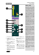
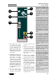
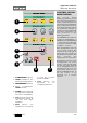
INPUT POD
The input pod is the
gateway to the remainder
of the signal processing of
the console. There are
three inputs, a mutually
exclusive microphone and
line input, and a tape input.
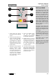
Note the different colouring
used to identify the
different signal paths of the
pod. Anything on a light
background is associated
with the LF path while
anything on a dark
background is associated
with the SF path.
The mic/line input normally
sends signal to the SF or
short fader signal path of
the console while the tape
input normally sends signal
through the LF or long
fader path of the console
unless this is reversed by
the FLIP switch.
There are two meters
associated with the inputs,
a 20 segment 0dBFS peak
reading meter showing the
tape input signal and a 3
segment peak reading
meter gives an indication of
the mic/line level.
Both the MIC/LINE and the
TAPE inputs have insert
points which can be
switched in and out of
circuit.
The Mic Input has a gain
control range of +6dB to
+60dB and the Line Input
has a range of -14dB to
+20dB.Switches allow for
Phantom Power, Polarity
Reversal and High Pass
filtering.
The TAPE input has a trim
control with a range of
±15dB.
There is a back illuminated
number at the bottom of the
pod for channel
identification.
1 20 Segment meter
2 3 Segment meter
3 INSERT IN places an
insert point in the TAPE
path
4 Tape Input TRIM control
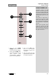
5 MIC/LINE switch -
press down to select the
line input.
6 MTR - press to show
the mic/line input on the
large meter and the tape
input on the small meter.
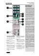
7 INSERT IN - places an
insert point in the MIC/
LINE path.
8 Mic/Line GAIN Control
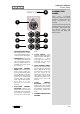
9 O Polarity (Phase)
Reverse Switch
10 48V Phantom Power
Switch. Turn the
loudspeakers down
before switching this on
or off !
11 High Pass Filter
Switch. A high pass
filter can be used to get
rid of any unwanted
low frequencies that
may be present such as
air conditioning rumble.
1
2
3
4
5
6
8
7
9
10
11