
User Manual


Operation Manual
28
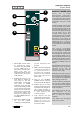
Input Strip
© 8.21
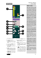
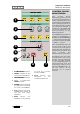
CONNECTOR
PANEL
The rear mounted
connector panel is where
the input, output and insert
point connectors are
located.
The microphone input uses
an XLR connector while the
line input, tape input and
the insert sends and
returns use Tip, Ring and
Sleeve jacks.
1
3
8
4
2
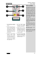
1 MICROPHONE INPUT.
Microphones or other
low levels inputs can be
connected to this input.
2 LINE INPUT. This input
can selected in place of
the microphone input.
Like the Tape input it is
suitable for high level
line sources.
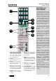
3 MIC/LINE INSERT
SEND . This is the insert
point send output for
the microphone and line
input. Signal is always
present here and can be
used as an additional
output. Only the Mic/
Line signal will appear
here and it is not
affected by the Flip
switch.
4 MIC/LINE INSERT
RETURN. When the
insert point is in use the
signal from the external
processing equipment
should be connected
7
5
6
here.
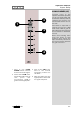
5 TAPE INPUT. The
output of the multi-track
tape recorder should be
connected here
although the input is
suitable for any high
level line source.
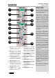
6 TAPE INSERT SEND.
This is the insert point
send output for the tape
input. Signal is always
present here and this
can be used as an
additional output. Only
the Tape signal will
appear here and it is not
affected by the Flip
switch.
7 TAPE INSERT
RETURN. When the
insert point is in use the
signal from the external
processing equipment
should be connected
here.
8
CHANNEL IDENTIFICATION
NUMBER.