
User Manual


Operation Manual
52
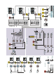
Patchbay
© 8.21
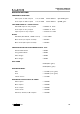
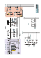
1.
CHANNEL
CONNECTIONS
Microphone input (XLR)
and Line input (jack)
connectors are located
on the rear connectors
panel behind each of the
input strips as on the
standard console (see
page 28). The Tape input
and insert send/return
jacks are omitted.
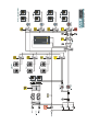
3. MULTITRACK
RECORD/ SUB GROUP
CONNECTIONS
These are located on the
underside of the console
adjacent to the PSU
connector. All console
interfaces are D-sub
female types wired to
the Tascam DA88
convention with 8
signals per connector
(see page 46).
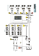
4. MULTITRACK PLAY
AND TIE LINE
CONNECTIONS
These are located on the
rear panel behind the
patchbay section. All
connectors are again D-
sub females wired to
the Tascam DA88
convention.
1-8
1-8
1-8
49-56
97-104
25-32
73-80
121-128
9-16 9-16
9-16
57-64
105-112
33-40
81-88
129-136
17-24 17-24
17-24
65-72
113-120
41-48
89-96
137-144
MULTITRACK A PLAYMULTITRACK B PLAY
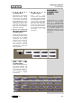
PATCHBAY
CONNECTOR
PANELS
Connections to studio
systems on consoles fitted
with the ASP8024PB
patchbay system are made
via the rear and bottom
connector panels generally
in a similar fashion to
standard consoles. The
exceptions to this are dealt
with here.
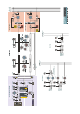
XLR and Jack
connectors associated
with the master module
are arranged in the same
way as the standard
console (see pages 39-
45) with the exception
of the sub-group insert
send/return jacks which
are omitted as these are
included on the
patchbay.
2. MASTER
CONNECTIONS