
Specifications


4 Audio Authority Model 1176BK User Manual
Audio Authority Model 1176BK User Manual 5
Stacking Components
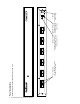
This diagram shows the parts and locations for
stacking components. The procedure must be
performed with the units upside down.
REMOVE BUS
ACCESS COVER AND
INSTALL ON LAST
EXPANDER
REMOVE FEET AND
INSTALL ON LAST
EXPANDER
BUS
CABLE
THREADED
STUDS
MODEL AVM-562
1172BK or 1176BK
BUS ACCESS
COVER
BUS ACCESS OPEN-
ING
The bus cable is
fragile! Do not crimp
or tug on the cable
as you install the
expanders.
2. Addressing and Initial Testing.
a. Set the Address dial on each Model 1172BK and/or 1176BK: set the upper-most Model 1176BKad-
dress to “B”, the next one to “C”, and so on. The AVM-562 Cat 5 output row is permanently ad-
dressed “A”. Follow 1172BK manual for addressing 1172BK. AVX-561 and AVX-661 require a differ-
ent address scheme; refer to the AVX-561 manual.
b. Temporarily plug in the power supplies of all units to a plug strip so that you can turn them all on
at one time. The opening screen on the Model AVX-562 display indicates that the unit is powered
and shows the number of expanders that have been recognized. If this number is different from the
number actually present, look for the bus not being fully plugged into a unit or a unit incorrectly ad-
dressed.