Installation and Operation Model AVM-562 High Definition Cat 5 Matrix
Installation and Operation Manual Model AVM-562 High Definition Cat 5 Matrix This document is consistent with features in firmware version 1.0 Audio Authority and the Double-A Symbol are registered trademarks of Audio Authority Corp. AVAtrix is a trademark of Audio Authority. Copyright August, 2008, all rights reserved. HDMI, the HDMI logo and High-Definition Multimedia Interface are trademarks or registered trademarks of HDMI Licensing LLC. Audio Authority® Corporation Lexington, Kentucky www.
Installation and Operation Manual Table of Contents Limited Warranty . . . . . . . . . . . . . . . . . . . . . . . . . . . . . . . . . . . . . . . . . . . . . 4 Warnings . . . . . . . . . . . . . . . . . . . . . . . . . . . . . . . . . . . . . . . . . . . . . . . . . 4 Introduction . . . . . . . . . . . . . . . . . . . . . . . . . . . . . . . . . . . . . . . . . . . . . . . 5 Getting Started . . . . . . . . . . . . . . . . . . . . . . . . . . . . . . . . . . . . . . . . . . . . . .
Warnings To reduce the risk of fire or electric shock, do not expose this unit to rain or moisture. ! • • • • • • • The exclamation point symbol alerts users to important operating and maintenance instructions in this booklet. Read this manual before installing or using this product. This product must be installed by qualified personnel. Do not open the cover—there are no user-serviceable parts inside. Do not expose this unit to excessive heat. Install only in dry, indoor locations.
Introduction The AVAtrix HD Cat 5 Matrix makes it easy to view any source from any video display at any time. Supported source signals include component video (YPbPr) up to 1080p, analog audio, and digital audio. Commercial venues, such as restaurants, offices, and retail stores, as well as private homes can benefit by using the AVAtrix to send selectable video and/or audio to remote locations.
Getting Started • Read through this entire booklet. • Register your purchase at www.audioauthority.com/register to activate your warranty and for future upgrade notification. Write the serial number (see AVAtrix rear panel) inside the back cover of this manual. • Unpack the AVM-562, assemble any expanders or accessories, and load batteries into the remote. • Install Cat 5 cables, terminate RJ-45 ends, and use a professional network cable tester to test the cables.
Suggested Audio Authority Accessories • Model 1176BK High Definition Cat 5 Matrix Router: connects to internal bus cable to add six wallplate/receiver outputs the AVAtrix. Maximum 36 Cat 5 receiver outputs per system. • Model 1172BK Audio Interface: provides an audio breakout point for the AVAtrix to connect an independent audio distribution system at the head end. Provides stereo analog audio or digital audio.
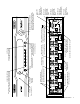
Panel Descriptions Shown on the page opposite are the front and back views of the AVM-562. Below is a view of the 1105BK Infrared Remote Control. Each AVM-562 includes one 1105BK; additional 1105BK Remotes may be purchased separately, or you may download the IR codes from www.audioauthority.com.
Audio Authority AVAtrix User Manual 9 Pr Pb Y AUDIO R L D REMOTE CAT 5 OUTPUTS 1 SOURCE INPUT 1 VIDEO IR A DIGITAL OPTICAL OUT POWER LED When lit, power is on B AUDIO R L D 2 SOURCE INPUT 2 VIDEO A DIGITAL OPTICAL OUT IR Pr Pb Y B AUDIO R L D 3 SOURCE INPUT 3 VIDEO A DIGITAL OPTICAL OUT IR Pr Pb Y B AUDIO R L D 4 SOURCE INPUT 4 VIDEO CAT 5 OUTPUT Connection for Cat 5 COMPONENT VIDEO INPUT wallplate/receiver YPbPr input port for position 1 ANALOG AUDIO
Installation You may wish to consult with a qualified custom electronics installer if you are inexperienced with UTP wiring and cable termination. You should be familiar with Cat 5e/6 cable termination tools, techniques, testing, and wire routing principles. 1. Assembling Expanders. Follow these steps if you are installing Models 1172BK, 1176BK or other expanders with your AVM-562 or AVX-562. Otherwise, skip to Step 3.
If you need to add more than two expanders, order AVM-562E or call Audio Authority Technical Support. MODEL AVM-562 REMOVE FEET AND INSTALL ON LAST EXPANDER The bus cable is fragile! Do not crimp or tug on the cable as you install the expanders. THREADED STUDS 1172BK or 1176BK BUS CABLE BUS ACCESS OPENING REMOVE BUS ACCESS COVER AND INSTALL ON LAST EXPANDER BUS ACCESS COVER Stacking Components This diagram shows the parts and locations for stacking components.
3. Rack Mount Adapters. Perform these steps if you are installing this product in a standard 19-inch equipment rack. a. Remove the cover screws adjacent to the front panel of each product and use them to mount Model 1192 (for Model AVM-562) or Model 1191 (for Model 1172/76) rack adapters. Be sure to place a spacer under the adapters at every screw location – see illustration. b. Use a straight edge to line up rack adapters on a stack of product before tightening the screws.
f. Adjust the Cable Length Compensation control on each wallplate/receiver according to the distance of that unit from the head end. Set the dial to the nearest number of hundreds of feet of cable distance (e.g. 200 feet = 2). During zone testing (see 7, below) it is recommended to use an HD source and display to fine tune each cable length compensation setting. Note: Setting compensation too high or low may result in picture dropouts or distortion.
7. Zone Testing. Plug the power supply furnished with the AVAtrix and each expander into its respective unit, and plug the power supplies into a plug strip so that all units can be turned on at one time. a. Power indicators on the AVAtrix, all expander units, and all installed wallplate/receivers should be on. If a wallplate power light does not come on, unplug the Cat 5 cables immediately and re-test them. b. The opening screen on the AVAtrix panel indicates how many expanders have been recognized.
Infrared Control Wiring Passive IR Emitter Source 1 A single emitter or blaster may be connected to the Main IR output jack, or use the individual IR output jacks at each source connection for discrete source control. Source 2 Source 1 Source 2 Source 3 Source 3 Individual Source Output Jacks (IR Router) Main IR Output Jack (3rd party IR from all zones) Do not use a powered connection block or signal amplifier with the AVAtrix.
2. Setting Up IR at the Remote Zones. a. Plug an Infrared Receiver into the 3.5mm jack on each wallplate/receiver that is to have IR source selection capability. (Use only compatible receivers without external power supply–see page 15 for more information.) b. Infrared commands returned from a zone to the AVAtrix can immediately select the source to be played on that wallplate/receiver output. Use the IR routing connections, or the main IR output from the AVAtrix (see 3 below). c.
e. The wallplate/receiver zone outputs are numbered 1- 6 on each output level, the first level being the AVM-562 outputs. The AVM-562 outputs are always addressed “A” and the next level, Model 1176BK, should be “B” and so on. An individual zone output is referred to as A2, or B5, etc. (See page 10.) 2. Custom Setup Highlights a. Settings. These options are convenient if the AVAtrix will be located in a visible area or around children.
b. Restriction Feedback for View-lock. When a user restricts the source, and restriction feedback is enabled, the video blinks to indicate that the command was implemented. If feedback is not enabled, the feature works without visible effect. c. Enter Custom Source Names. These names are the “labels” shown on the AVAtrix panel display representing the six input positions. Short names may have up to four characters (letters, numbers, spaces or symbols).
Setup Menu Chart • To access the menu, press MENU on the IR remote; or press and hold the knob, and touch the front panel MENU key. • To perform password protected operations, enter “2-3-6” and ENTER on the front panel. Settings Lockout Front Panel Keys Lockout all front panel keys except for Display and the key sequence for Setup Menu access. Lockout Front Panel IR Detector Detection ignores any IR commands visible from the front panel IR window; IR input jack on rear is still active.
Operation The AVAtrix allows you to select the source being played at each Cat 5 wallplate/receiver zone from the head end, and if the zone location is equipped with an infrared receiver, the source can be selected using an infrared remote control at the zone. Two operation screens are available: Residential and Professional. Use Professional mode to control the zones from the head end. Use Residential mode if the AVAtrix is visible at the local zone.
Remote Zone Operation: Key Sequence Examples The key sequences for several operations using the 1105BK IR remote control from the Cat 5 wallplate/receiver zone are shown below. The zone must be equipped with a compatible IR receiver. Changing the source on the zone output Press the desired source number key. Activate VIEW-LOCK Press LOCK, then press VIEW-LOCK. No other zones can select the source selected at this zone, and zones viewing this source are locked out.
Appendix A: Troubleshooting Symptom Causes and Solutions Flashing POWER LED on Expander • Improperly terminated Cat 5 cables – Use professional cable tester and re-apply cable ends • Bad power supply – Install new supply • Damaged Cat 5 receiver – Disonnect all Cat 5 cables and observe POWER LED • Bent pins on internal bus cable connector – Call Audio Authority for assistance No video or IR control after adding expanders • Incompatible firmware versions – Upgrade to latest firmware (see www.
Appendix C: How to Use Diagnostic Modes To access diagnostic modes, enter Setup Menu (press the knob and touch MENU) and select DIAGNOSTICS at the bottom of the menu. Expander Address Diagnostic This diagnostic can be used to determine whether all of your AVAtrix expanders are set to the correct address. Enter this diagnostic mode and then turn the address dial on the rear of each expander until the “X” on the screen is under the correct address.
Appendix D: RS-232 Serial Protocols Model AVM-562, and 1176 expanders can be controlled via RS-232 from a PC or dedicated controller. Two different RS232 serial protocols are available; the Abbreviated Command Set is simple, and one-way, and the Extended Command Set has more commands and reports all system changes through the serial port, regardless of the origin of the command. Use commands from either or both protocols. Specifications The RS-232 control port on the AVAtrix is fixed at 9600 baud.
Abbreviated Command Examples The general format of commands is as follows: Definition of output(s) to be acted upon (Zone, Group, Main, All Address letter of output (row), when selecting Cat 5 output Cat 5 output port number (column), when selecting Cat 5 outputs Source number to be routed to the output(s) ZC23 Example 1. To route source input 3 to the main AVAtrix output, send the following command: M3 (The AVAtrix selects source 3 to its main output) Example 2.
Extended Command Set All valid commands receive a response, and all changes in the AVAtrix system are reported. In the “Command” column on the next page, actual commands are shown in upper case, and variables are represented by lower case bold characters (commands are not case-sensitive). Command Definitions (Extended) Command: String received by the AVAtrix from the controlling hardware. Commands are not case sensitive and should be 8-bit with No parity.
Query Commands (Extended) Query: Response: Description: [?,C,Rx,On] (Rx,On,Im) Query unit connection [?,C,M] (M,Im) Query main connection [?,C,X] see below Query all connections [?,{L,U},P] (P,{L,U}) Query status of panel lockout [?,{L,U},I] (I,{L,U}) Query status of internal I/R lockout [?,{L,U},A] (A,{L,U}) Query status of AutoSelect lockout [?,{+,-},B] (B,{+,-}) Query status of Display blanking [?,{+,-},P] (P,{+,-}) Query status of Display Screen [?,{+,-},A] (A,{+,-}) Query s
2048 Mercer Road, Lexington, Kentucky 40511-1071 USA Phone: 859-233-4599 • Fax: 859-233-4510 Customer Toll-Free USA & Canada: 800-322-8346 www.audioauthority.com • support@audioauthority.com v 1.