
User manual


12 Audio Authority AVAtrix User Manual
Audio Authority AVAtrix User Manual 13
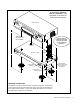
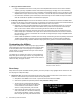
3. Rack Mount Adapters. Perform these steps if you are installing this product in a standard 19-inch equipment rack.
a. Remove the cover screws adjacent to the front panel of each product and use them to mount Model 1192 (for
Model AVM-562) or Model 1191 (for Model 1172/76) rack adapters. Be sure to place a spacer under the adapt-
ers at every screw location – see illustration.
b. Use a straight edge to line up rack adapters on a stack of product before tightening the screws.
CAUTION! This product will be damaged if
spacers are not used on every adapter screw.
IMPORTANT!
Do not mount adapters
without spacers
4. Setting in Place. Place the AVAtrix on its shelf or in the rack. If rack mounting, secure it to the rails with the screws
supplied with the rack adapter kits.
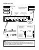
5. Audio and Video Hookup. Connect and test sources with the local video display in these steps.
a. Connect each source unit to its respective set of AVM-562 input jacks.
b. Use high quality cable and keep the runs under 6 feet if possible, especially for component video connections.
c. Connect either, but NOT BOTH optical and coaxial digital audio. Connect all the other signals available from the
source unit: component video and analog audio.
d. Connect a video display and audio system to the Local (Main) Output jacks. Use optical and/or coaxial digital
audio outputs. The AVAtrix does not convert digital audio to analog audio, so connect analog audio to TV’s
inputs if required.
e. Turn on the sources and AVAtrix temporarily for an initial test. Select each source to the local TV and sound
system to verify basic functions. Remove power and continue installation.
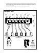
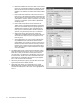
6. Cat 5 Zone Connections.
a. Pull two lengths of good quality Cat 5e or Cat 6 UTP cable from the main sys-
tem to each receiver location. Shielded Cat 5 cable may be used, but offers
no performance advantage.
b. Carefully mark cables of each pair A and B; if they are connected incorrectly,
damage to the wallplate/receiver may result. It is best to use a different cable
jacket color, or label each end for A and B to ensure proper connection.
c. Install RJ-45 plugs using EIA-568B pairing (pins 1-2, 3-6, 4-5, 7-8). Check
each cable with a professional network cable tester before plugging it
into the AVAtrix, even when using pre-made cables. Continuity testing is not
adequate! The twisted pairs must be properly matched for balanced line
transmission.
d. Carefully plug the pairs of cables (A and B) into the correct A and B AVAtrix
output jacks.
e. Connect cables to each wallplate/receiver. Be sure to plug cable A into jack A and cable B into jack B. Leave the
wallplate Cable Length Compensation controls accessible until after zone testing.
1 2 3 4 5 6 7 8
W-O O W-GR BL W-BL GR W-BR BR
Pair 2 Pair 4Pair 1
Pair 3
T568B Pair Assignments
Modular Jack (RJ-45)
1 2 3 4 5 6 7 8
W-O O W-GR BL W-BL GR W-BR BR
Pair 2 Pair 4Pair 1
Pair 3
T568B Pair Assignments
Modular Jack (RJ-45)
!
!