
Specifications

FCS1362 Page 33 of 74 © Nov 2010
Antenna positions should be planned to achieve best separation between antennas while maintaining a
suitably sized ground plane for each one – see Appendix F.
There will be a point where multi-coupling (antenna combining) techniques may become cost effective in
maintaining performance. This should be a part of the vehicle installation design process.
4.2.3.1. Antennas and sunroofs
If a sunroof is fitted, then the antenna should be mounted at least a quarter wavelength from the opening,
see section 4.2.2 for wavelengths. Care should be taken to ensure the selected position does not foul the
sunroof or its operating mechanism.
4.2.3.2. Fuel filler caps
The antenna location must be a minimum of 30 cm from the edge of the vehicle’s refuelling system/fuel
filler cap to account for the possible effect of the radiated electrical field as a source of ignition.
Consideration should also be given to the potential danger from an antenna tip being positioned at or
below eye level where, for example, it could cause injury to a person refuelling the vehicle.
4.2.4. Fitting antennas
Fitting the antenna depends on the antenna type and the vehicle it is being fitted to.
4.2.4.1. Panel mount antenna
This antenna type requires a hole to be drilled in the vehicle body in order to mount the assembly. See
section 2.11 for guidance on drilling holes.
Before fitting the antenna in the desired location check for adequate clearance under the panel for the
cable and ensure the installation will not interfere with the structure or operation of the vehicle.
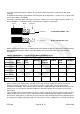
A conventional panel mount antenna is mounted vertically on a horizontal ground plane. The ground
plane is a component of the antenna system provided by the vehicle’s body panel.
Ideally the antenna will be mounted in the centre of a ground plane with a radius of at least one quarter
wavelength at the lowest frequency band being used. On lower frequencies (e.g. low band) this ground
plane radius may be difficult to achieve due to larger wavelength. In this case the antenna may need
adjustment of length, usually shortened, to compensate for the smaller ground plane, see section 4.8
testing antennas.
De-burr the hole and remove an area of paint/primer from the underside of the panel to ensure a good
earth connection for the antenna mount. Petroleum jelly or a similar substance should be applied to the
exposed metal to prevent subsequent corrosion occurring.
Care should be taken not to over-tighten the mount as this could cause distortion of the panel.
4.2.4.1.1. Panel mount antenna on vehicle with electrically isolated chassis
It is not common but it may be necessary to install a panel mount antenna to a vehicle with an electrically
isolated chassis.
Using a standard panel mount antenna in this case will compromise the chassis isolation by providing a
path for a negative potential to the chassis. This isolation break down can be overcome by fitting a
suitable antenna which has no direct contact between vehicle chassis and coaxial connector or cable.
In exceptional cases a DC path blocking device, also known as a ‘braid breaker’, may be introduced in
the coaxial cable feed as close to the antenna as possible. It should be noted that these devices are
usually frequency dependent so care must be taken that the unit is suitable for use at the intended
frequency.