
Specifications

FCS1362 Page 35 of 74 © Nov 2010
• The antenna should be mounted, wherever possible, so as to maintain vertical polarisation
• If mounted horizontally it could incur significant cross polarisation loss and produce large null areas in
the radiation pattern
• Consideration given to the attenuation of signal and radiation pattern distortion caused by being fitted
behind trim material (e.g. the ‘A’ pillar or dashboard covering)
• A radiating antenna should be installed as far away as possible from any ECU or an airbag/SRS
deployment system to minimise the risk of radiated (EMI) susceptibility problems.
The upper limit for VSWR may have to be increased for this type of antenna due to its design and
mounting position. A limit of 2.0:1 is acceptable for cellular GSM/3G, but may have to be higher for
specialist mobile radio types, see section 4.8.2 for VSWR measurement.
See Appendix G for information regarding antenna performance of covert antennas.
4.2.4.6. GPS antenna
A GPS antenna function is to receive only. This means that in respect of radiated EMI issues its mounting
position does not have the same constraints as that of a radiating antenna.
This type of antenna is typically active with a low noise amplifier (LNA) powered by a phantom feed up
the antenna coaxial cable, supplied by the GPS receiver.
Some systems can use an alternative type of GPS antenna that combines the GPS receiver and antenna
in one unit and this is often referred to as a GPS mouse. This device is self contained, so there is no
connecting coaxial cable and can commonly be divided into two distinct types:
• Permanently fitted and usually externally mounted - this type has a multi-core cable to connect to the
terminal equipment which supplies power to the GPS receiver and carries serial data position
information to the terminal.
• Portable unit – this type is generally battery powered and provides serial data position information
over a low power wireless link that typically operates in the unlicensed ISM band.
Antennas for GPS reception need to have a clear view towards the sky to enable acquisition of satellite
signals. The location of the antenna will have a marked effect on effective GPS performance. See
Appendix E for an example E-plane diagram for a GPS antenna.
It should be noted that vehicle glass can be metallised (tinted) or have fine mesh heating elements. This
will have an adverse affect on the performance of a GPS antenna and may require it to be fitted in a
specific place, for example in a clear view area aperture for a road toll transponder, or even externally.
Consult the vehicle and/or glass manufacturer for guidance.
4.2.4.7. Temporary antennas
These can include boot mount, magnetic mount, gutter mount and window clip types.
Care should be taken when routing the coaxial cable through door or boot openings to minimise risk of
damage to the cable.
Before a magnetic mount antenna is fitted both the underside of the base and the selected body panel
surface should always be cleaned so as to avoid damage to the paint work.
See section 2.8.2.4 on safety when using temporary antennas with magnetic bases.
4.2.5. Coaxial cable to antenna
A suitable coaxial cable of the correct impedance, usually 50 ohms, correctly terminated with a suitable
connector should be used to provide a continuous run between the antenna and the radio equipment.
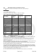
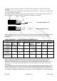
Table 2 below shows the loss figures for the most common types of coaxial cable used in mobile
installations.
It should be noted that, although they may have the same type designation, such as RG58, there can be
a variation in quality of construction and performance of cable from different suppliers. It is important to