
Specifications


FCS1362 Page 63 of 74 © Nov 2010
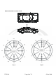
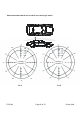
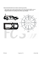
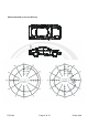
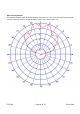
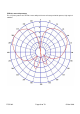
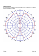
Appendix E: Antenna radiation patterns
Typical H plane radiation patterns for various antenna positions on a typical saloon car are shown in the
following figures. These illustrate the typical trade off between good omni-directional performance and
location of the antenna.
For all the diagrams:
• Plot A on the left is typical for a low band PBR (66-88MHz) wavelength whip.
• Plot B on the right illustrates a typical 900 MHz band cellular GSM/3G mobile phone antenna with
gain.
See sections 2.8 and 4.2 for guidance on mounting the antenna on the vehicle.