
Specifications


FCS1362 Page 71 of 74 © Nov 2010
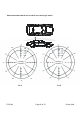
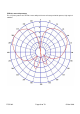
Appendix F: Multiple antenna installation
Image and data supplied by NPIA
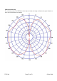
The diagram below illustrates an installation with multiple antennas. Although the example is of a typical
hatchback police vehicle the principle applies to any vehicle with additional antennas and items installed
on the roof.
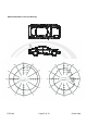
The antenna positions shown on vehicle roof below have been selected to achieve an effective ground
plane and best separation between the antennas and roof clutter.
Diagram and information supplied courtesy of the National Policing Improvement Agency (NPIA).
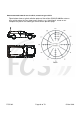
GPS receive
aerial
The VHF aerial on
the centre line of
the vehicle 16.5 cm
from the rear of the
roof
The UHF aerial on the
left-hand side 33 cm
from the centre line of
the roof and 16.5 cm
from the rear of the roof
Light bar
The TETRA aerial on the
right-hand side, 33 cm from
the centre line of the vehicle
16.5 cm and from the rear
of the roof
Petrol
filler cap