
User manual


4 Audio Authority
®
Model HMX-244 User Manual
HMX-244
VIDEO MATRIX
1 2 3 4
ZONE 1
OFF
1 2 3 4
ZONE 2
OFF
1 2 3 4
ZONE 3
OFF
1 2 3 4
ZONE 4
OFF
AUTOPOWER
ZONE
REMOTE CONTROL
HMX-244 VIDEO MATRIX
1
4
2 3
SELECT
SOURCE
Model HMX-244 4x4 Video/Audio Matrix
POWER
POWER
5V DC
ZONE 1
OUTPUT
ZONE 2
OUTPUT
ZONE 3
OUTPUT
ZONE 4
OUTPUT
HDMI SOURCE INPUTS
IR
SOURCE 4
INPUT
SOURCE 3
INPUT
SOURCE 2
INPUT
SOURCE 1
INPUTIR IR IR IR
RS-232
TMDS
DDCHDMI
A
B
TMDS
DDCHDMI
A
B
TMDS
DDCHDMI
A
B
TMDS
DDCHDMI
A
B
IR
SELECT SOURCE
1 2 3 4
ZONE
4
SELECT SOURCE
1 2 3 4
ZONE
3
SELECT SOURCE
1 2 3 4
ZONE
2
SELECT SOURCE
1 2 3 4
ZONE
1
E
G
A
F
B
C
D
J
I
H
K
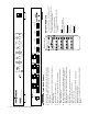
HMX-244 FRONT AND BACK PANELS
A Infrared Receiver - accepts commands from IR remote controls
B Source Selection Button - push button cycles through available
source inputs
C Selected Source Indicator Light - indicates the selected source in
the specied zone
D Power Switch - turns matrix off or on
E Power Jack - connect included 5.5V, 4A power supply
F HDMI Zone Output - connect directly to display and/or audio
system in nearby zone
G Cat 5 Zone Output - connect to Model 1380R zone receiver for
long cable runs to more distant zone. Either TIA/EIA 568A or
568B standards may be used provided it is straight through and
not crossover.
H Source IR Output Jack - repeats IR commands received by
1380R - connect IR emitter to source
I HDMI input for source
J IR Input Jack - connect Model 804-052 IR receiver (sold
separately) for remote IR input
K Serial Port - accepts RS232 commands from home automation
devices
HMX-244 IR REMOTE
L Power on/off button - turns matrix on or off
M Auto mode - switches to lowest numbered
output with video signal present
N Source buttons for zone 1
O Zone off button- deselects all sources
from zone
N
L M
O
Note:
Use only 5V demodulated IR
receivers such as Model 804-052
(sold separately)
IR Receiver pinout
Tip = +5 Volts
Ring = Data
Sleeve = Ground
IR Emitter pinout
Tip = Signal
Sleeve = Ground